Hybrid Physics Labs with “Astronauts” and “Experts”

Hybrid Physics Labs with “Astronauts” and “Experts”

College physics labs were conducted with half the students physically in the room, each working with a remote lab partner. Since this is similar to how NASA astronauts perform experiments on the International Space Station (ISS), those roles came to be called “Astronauts” and “Experts.”  Emphasizing the connection Astronauts, NASA, and the ISS seems to have helped students deal with the unusual circumstances of labs conducted during the COVID-19 pandemic.


The SARS-CoV-2 pandemic created some significant challenges for higher education, especially for laboratory classes, which involve hands-on interaction with equipment and face-to-face collaboration with lab partners. But as it turns out we were able to meet those challenges and execute close to our full set of weekly physics labs, with some modifications and inconvenience but with no significant disruptions. Since this worked for us we want to record the details of how we did it and share that information with others in case it proves to be helpful.

The basic idea was to have half the students working with the apparatus in the room, appropriately distanced,  while the other half joined the class remotely via a video teleconference.1 As is often the case in a normal lab session, the instructor presented information and instructions to the entire class at the beginning, though to minimize this students were also provided with pre-recorded videos about the equipment and procedures, which they were supposed to view before class. After the initial briefing, students were then paired up as lab partners, with one of them in the room and the other remote, using the break-out group feature of the teleconferencing software. Each pair of students then collaborated to perform the experiment: taking measurements, recording and sharing data, and analyzing and interpreting their data together.

There were many small technical details that had to be worked out to make this all possible. Only after we had it all working did one of us realize that this is similar to how NASA astronauts perform experiments on the International Space Station (ISS). While astronauts are intelligent and well trained, they are also busy and cannot be experts on every experiment they perform  — and they perform many during a typical mission. During an experiment the astronauts are therefore linked by audio and video to one or more experts on the ground (see Figure 1), and together they go through the necessary steps to collect the required data, and to deal with the inevitable questions or difficulties that always show up during any experiment. (See also Astronaut Log below for a good video.)

Figure 1: Astronaut Peggy Whitson working with “expert” Nicole Dufour from the Veggie experiment on the ISS in 2017.

We found it useful to play-up the parallels between this lab format and the way astronauts work with experts to perform experiments on the ISS, not because it helped teach physics concepts better, but because we felt it helped make this unusual way of doing lab experiments seem less unusual. Given all the other changes to society due to the pandemic, making some of it seem more normal, or even cool, seemed useful.  And it seemed to have had that effect. Students responded positively to being called an Astronaut or an Expert, and in some cases students even wore clothing with a NASA logo or a space theme. Feedback on the end of semester course evaluation was positive (see Student Feedback below).

Getting this all to work required a lot of particular choices regarding technology and how to use it. As they say, the devil is in the details. Those details are listed below.

Working out all the technical details that made this all possible raised a number of fundamental questions about teaching physics and physics labs. What are the elements of the course that were most important to preserve?  What could we modify without doing too much pedagogical damage?  Why not just go full remote? Reflecting on these questions made us more aware of some things that we already knew intuitively. Physics labs give students hands-on experience with the concepts they are learning or will soon learn in the related lecture course, and the lab experiments provide live demonstrations of the principles in action. But there’s more than that. Physics is… physical, and so students learn better when they can actually see what happens in a live experiment and can control and change parameters of the system. Our labs also involve data analysis, but there is much more to the class than just data analysis; it is direct, experiential learning. Labs also provide students with many small challenges they have to overcome to get the equipment working, and that is also valuable experience. Although it is often possible (and sometimes desirable) for students to work alone, lab students often work together in pairs (or sometimes three’s). Sometimes this is necessary just to work a particular piece of equipment, but in any case working together adds to the educational experience, just as peer instruction is a useful addition to the lecture course. Learning to work together with someone else on a common task or project is a valuable skill in any academic subject, as well as in life in general.

Finally, we found that some of the changes we made due to the pandemic turned out to be useful in general and will be kept in the course after the virus has been subdued. So we hope and expect that some of the details below will be useful even after this plague has passed.


The Details

  1. Physical Layout: The physical modifications to the laboratory were minor (mainly moving tables and chairs), and are described in more detail in Appendix A. We were able to arrange the rooms to allow half the normal number of students to be in each room at the same time, with at least 2 meters (over 6 feet2) between students (or the instructor) when they were at a normal working position at the middle of the table. It was expected that students might get closer from time to time as they worked with the equipment, and that the instructor would move through the classroom to provide assistance, even if they tried to keep some distance between them and the student while doing so. Every student and instructor wore a mask at all times. (Students could leave the building for a mask break during the 2 hour class period, but few chose to do so. The instructor could also go to another room or office for a mask break — see Remote Instructor Assistance below)
  2. Mission Roster: Keeping track of the students who would come in to the room (the “Astronauts”) and those who would join remotely (the “Experts”) added complexity to class organization, which was managed to a certain extent with a “Mission Roster” form (pdf here). Figure 2 shows the top of the form, which provided for 10 groups of 2 students.
    Figure 2: Mission Roster for planning each class meeting (top only).

    The first line, marked “A” for Astronaut, is for the name of the student who will be in the classroom. The second line, marked “E” for “Expert” is for the student who will be partnered with them. For the first day of class, students were paired by common declared academic major. After a few weeks the pairings were changed, either by necessity or to give students experience with working with more than just one other person.

    It was wise to use pencil to fill in the chart, as changes sometimes had to be made shortly before class started. After a few class meetings, this record of who had played which role helped when balancing out role assignments for future class meetings.

  3. COVID-19 Screening: in order to come onto campus every student had to complete a daily on-line health screening. The date of the last successful screening is shown to the instructor in an on-line course roster. It was important to verify well before class that the “Astronaut” students had all passed their screening on the day of class. The check boxes on the Mission Roster form were used to record a successful daily screening. In most cases when a student had not filled in the form early in the day they at least completed it within an hour before class, but in some cases students could not attend because of the need to quarantine due to possible exposure to someone who was infected, or even if they just reported feeling a bit under the weather. In that case the instructor had to quickly arrange for someone else to come in as an “Astronaut”.
  4. Pre-Lab Videos: Brief videos were prepared showing the equipment to be used in the experiment(s) and demonstrating the procedure. Students were encouraged to view these before class. We found the free Open Broadcasting Software (OBS, at https://obsproject.com/) useful for preparing these videos, especially for multi-camera shots. We also found it was better to make several short videos focused on a single narrow topic rather than one longer video containing everything. A lecture capture camera already installed in the room proved to be less useful than webcams that could be positioned close to the equipment. Student feedback was favorable (see Student Feedback below).
  5. Video Meeting Software: Our campus uses Blackboard for course content management, and that includes a video meeting system called Blackboard Collaborate Ultra (BBCU), so that was used for all class meetings. One important feature of BBCU is that it makes it extremely easy to share a second camera, either for use as a document camera (see Document Camera below) or for the remote lab partner to get a better view of what is going on (see Second Camera below). Other video meeting software could have been used, but it should be noted that while Zoom also makes it fairly easy to share a second camera, WebEx does not.[3 I will link here to another page that gives more details for a wide range of Video Meeting systems.] Having the video meeting integrated into the standard course content management system made things much simpler. One disadvantage of BBCU is that it only shows a few faces at a time during a video meeting, not the whole “Brady Bunch/Hollywood Squares” matrix display of everybody. But given that most students wanted to keep their cameras off this was not a significant issue.
  6. Coms Check: Instead of simply calling the roll at the beginning of the class, we had “Coms Check,” (Communications Check) where each student answered when their name was called, to verify two-way audio communications, and they also turned on their camera to verify that video worked. Most students preferred to join the class with cameras off, at least until they began working with their partner (and many even after that phase of the class had begun).
  7. Room Audio System:  Audio feedback was a problem if any of the laptops in the room were in the video meeting and did not have their speakers muted during the initial lab briefing, when the instructor was talking to the class with students both in and out of the room. It was therefore important to have everyone in the room mute their sound, and the key sequence for this (Fn+F1 for Dell laptops) was written on the whiteboard.We initially tried to use wired or wireless headsets for the instructor to avoid audio feedback during the initial briefing, but that proved to be unnecessary, as our Instructional Media Services (IMS) team was able to configure the room audio system so that remote student audio was broadcast on the room speakers, but there was no feedback. That way remote students could ask a question and everyone in the room could hear them. This was accomplished using a Focusrite Scarlett 2i2 (3rd Generation).
  8. Remote Student Location:  The “Experts” who joined the class remotely were generally at home or in their dorm room.3  We realized late in the semester that we could have the Expert lab partners in any other classroom on campus that would allow them to join the video meeting while maintaining appropriate distance — and we had such a room right next to the lab. (These students would, of course, have to successfully pass their daily screening to be allowed on campus.) We only used this occasionally when there was confusion about which student was scheduled to be the “astronaut” or whether or not a student was actually cleared to be on campus, but we hope to use this more next semester. In general though, when offered the opportunity to join the class from an on-campus room but not the lab room, students preferred to work from home.
  9. Seating Chart: The tables in the room were numbered, and the chart shown in Figure 2 (see Appendix A) was attached to the Instructor’s station. During Coms Check the instructor recorded on the Mission Roster form the number of the table at which each student sat, in case that information was needed for contact tracing (thankfully it never was).
  10. Group Assignments: Pairs of students were assigned group numbers ahead of time, from 1 to 9, which were used to assign them to break-out groups. BBCU uses numbered break-out groups. It turned out to be most efficient to tell the students their group number during the Coms Check (see Break-Out Groups  below).
  11. Recording Class Meetings:  Blackboard Collaborate Ultra made it easy to record class meetings, which allowed a student who missed class to view the same material presented to the class before performing a make-up. It could potentially also allow students to go back and review the instructor’s briefing, but we don’t know if anybody did. There was no point in continuing the recording after the briefing, though it was often the case that the instructor forgot to stop recording.
  12. Document Camera:  Several instructors used a document camera at the instructor station to present the initial lab briefing. Our particular document cameras fed output via HDMI to a projector in the room, so that students in the room were able to see it, but with an additional USB cable the same video was fed to the computer and into BBCU and shared as a second camera, allowing the remote students to also see what the instructor was writing. Details on how this worked are in a separate article, Using a Document Camera for ‘local+remote’ Instruction.
  13. White Board Camera: Other instructors preferred to present their initial lab briefing using the classroom white board. They presented to a camera set up on a tripod, and limited their use of the white board to only that part which was visible to the camera. Students in the room could see and hear the instructor, as could remote students. (Students in the room could also see the camera view on the laptop on their desk if they did not have a good view of the particular part of the white board the instructor was using.)
  14. Laptop Computers: We were fortunate that the computers in our two introductory labs had recently been updated to laptops running Windows 10 which included built-in cameras, which facilitated face-to-face video collaboration. A third lab room had been upgraded to small footprint desktops, and these required only an added camera to be used for videoconferencing. In any case, these computers were available for data collection and analysis, using Vernier’s Logger Pro software. The student in the room could easily share their screen with the remote student within BBCU. (See also Sharing Data below).
  15. Break-Out Groups: Blackboard Collaborate Ultra allows the video meeting to be broken up into numbered break-out groups. At first the instructor would assign students to these break-out groups after the lab briefing had been presented, but this took several minutes, and only took effect when the instructor pushed a final confirming button. We found instead that we could tell the students their group number, check a box that allowed them to change groups, and then have the computer assign them all to random groups of 2. They then quickly changed to the correct group.
  16. Ear Buds: At first we anticipated elevated noise in the room when students started talking to their remote partners, but with only half the students in the room it was actually quieter than a normal lab session. In testing during the summer we found that the built-in laptop microphones picked up sound from all around the room and did not give particular emphasis to the closest speaker. We therefore provided each student with a set of corded ear buds ($3.08 each on Monoprice, plus $10 shipping) which had a built-in microphone in the cord. The primary advantage of this was that the microphone close to the speaker’s mouth enhanced their speech over the other sounds in the room. The ear buds also helped the student hear their remote partner over the sound in the room.  About 70% of students used the provided ear buds, while 30%  chose to use their own devices, which included Bluetooth headsets or earbuds, since our laptops support Bluetooth.
  17. Second Camera: The built-in camera in the laptops provided on each table could allow lab partners to communicate face-to-face to collaborate on the experiment, but it was not very useful for viewing the equipment. We therefore provided each station with a second USB webcam which could be mounted on a stand and aimed at the equipment, so that the remote student could see more of what was going on. As already noted, BBCU makes it very easy for the local student to share the extra camera (as well as sharing the screen or a particular window on the screen). In the Physics 2 Lab we used the Logitech C270, which retails for about $40 each. In the Physics 1 Lab we used  a mixture of Logitech C910 and Logitech C920 cameras, which are more expensive, but we already had them available for video motion experiments. We chose the C910/920 cameras for the Physics 1 Lab because they have a wider field of view which was more helpful for the Mechanics experiments in that class, while the experiments in the Physics 2 Lab, which deal with electricity, magnetism, and optics, did not suffer from the slightly smaller field of view.During the summer, before the fall semester, we experimented with using a commodity home “nanny camera” because of concern that the market for webcams would be tight. That worked, but required students to access the camera via a separate app that they would have to install on their personal mobile device. When webcams became available we turned our focus to those. Details of the investigation of using “nanny cameras” are described in the separate article Potential Use of Steerable Consumer Home Cameras for “local+remote” Laboratory Instruction.
  18. Camera Stands: We experimented with a variety of different stands for holding the cameras, and even let the students try out different methods on their own. One of the best stands was a flexible “gooseneck” from AboveTEK  priced at about $30 each. (This also makes a good stand for a home document camera.)We attempted to build something similar using flexible metal sheathed electrical cable, but it did not work as well; one notable problem was that the camera vibrated more. In the end we settled on using our existing stock of bench clamps and vertical and horizontal metal rods held together with rod clamps, with the camera held in the fingers of a test tube holder. For some experiments in the Physics 2 Lab we mounted the test tube holder on a table top stand that presented a vertical metal rod about 2 feet long. This was useful for positioning the camera to view meters or Oscilliscopes.
  19. Remote Instructor Assistance: Once students were put into their break-out groups and began working in pairs on the experiment, it was possible for the instructor to go to their office or another room and join the class remotely. This  allowed them to visit each group to see how well the second camera was positioned to support the remote collaborator, to ask if they needed assistance, to answer any questions, and it also gave the instructor a mask break.Remote access for the instructor had to be configured before class, by using a “guest” link to the video session in Blackboard Collaborate Ultra to log in to the video meeting from the other room ahead of time, and then using the instructor’s account to promote that guest to “Moderator” status (giving them the same powers as the instructor).4 When logging in to the video meeting as a guest a name is requested, to be displayed on the video. (For authenticated users this info is just taken from the account info). To avoid confusion with the instructor’s account that was used in the classroom, the name given for this connection was “Mission Control.”
  20. Sharing Data: In some cases students collected data by writing down measurements in a notebook (a good task for the Expert, but we let the students decide how to do it). In other cases data and graphs were collected in files, and  a mechanism was needed to share those files from the laptop in the classroom with the remote student. The files also had to be transferred to some place that the Astronaut could use them later, because the classroom laptops were configured to reset after every logout, deleting any files a student had put on that computer. Several alternatives were available, but the easiest was for the Astronaut to save the files to a folder in their campus Google Drive account5  The Astronaut then shared that folder with their lab partner, and both had a common copy of the data. Sharing a folder once proved to be much easier than sharing individual files. When students were assigned a different lab partner they were reminded of this and encouraged to create and share the folder ahead of time.
  21. Astronaut Log: Following the idea that promoting the connection between our unusual lab format and how experiments are conducted on the ISS would help our students feel that it was all slightly less strange, one lab section set up a news feed about the ISS using Google Classroom (linked from the course web page in Blackboard, which does not have a news feed feature). This was open to all lab students, and indeed some joined from other sections, but it ended up being only posts by one instructor of current events and other relevant links about the ISS. It was totally optional and it was made clear to students that there was no grade for participation. During the semester there was always something in the news about the ISS, including a mysterious air leak. Using Google News and “Following” the topic “International Space Station” provided a steady stream of current events related to the ISS. YouTube has a wide variety of videos from the station. There is also a wealth of information about experiments on the ISS available from NASA. A good place to start is the ISS Researcher’s Guide Series.One of the best resources was the video in Figure 3, which shows an astronaut on the ISS cutting leaves off of plants grown in space while collaborating with a team on the ground. This really demonstrated how astronauts and experts were able to work together. If nothing else it showed our students that it was possible and gave them a working model.


    Figure 3. Video from 2017 showing experts on the ground working with an astronaut on the ISS to perform an experiment.

  22. Air Track pumps: Some experiments in the Physics 1 Lab used air tracks to reduce the friction of metal carts, which float on a cushion of air. The pressurized air is provided by a pump, much like a vacuum cleaner but run in reverse, and connected by a similar hose. We had some concerns about the blowing air spreading the virus from an asymtomatic or presymptomatic student, either because the air would spread the virus directly, or because the virus might be picked up by the pump and then blown out by the air track. After discussions with someone from our campus Health and Safety office it seemed that the air flow directly from the air track would not go beyond the work area of the student, due to the extra distance put between students. So that was not a big concern. Spreading the virus by droplets might be enhanced by the pump picking up the droplets and ejecting them into the room, but droplets sink to the floor,6 so we made sure that the pumps were always up on the table (which was already the case for all but one pump). We further put strips of vacuum cleaner bag to act as a filter over the intake of all pumps. We have no idea if these steps were actually useful, but they were relatively easy to implement and they do no harm.
  23. Clear Plastic Partitions: At one point it looked as if students using the air tracks in the Physics 1 Lab might spend more than just a brief time within 6 feet of each other while collecting data. We therefore hung thin clear plastic sheets7 between some student stations. This was relatively easy to do by folding the top of the curtain over a length of wooden dowel and then clipping it with common binder clips. This was hung from the ceiling using thin wires of a fixed length (insured by using a jig) with loops in both ends. The bottom loops were connected to the binder clips using common paper clips, while the top loops were clipped to the metal runners between ceiling tiles using Suspended Ceiling Hooks purchased at Home Depot. After some rearrangement of the air tracks we were able to have most students spend most of their time collecting data while at least 2.0 meters away from each other, but we left all of these partitions in place anyway.
  24. Room Ventilation: Our lab rooms are in a new building which has a variety of modern features, including very good ventilation.8 The thermostats in the lab rooms also monitor and display the CO2 level in the room, and experiments showed that if that level was elevated then the rate of ventilation would automatically increase — the fans could be heard spinning up within a minute of a significant increase. One consequence of this is that if an instructor felt the need to increase the ventilation manually then they could do so simply by blowing on the thermostat with a straw. This was tested, but never actually put into practice during a class. In any case, using CO2 levels as a proxy for measuring the need for ventilation is a useful tool.

Student Feedback

Student feedback on the “Astronauts & Experts” approach was generally positive. In the Student Evaluation of Instruction (SEI) survey for one section of the Physics 2 Lab at the end of the semester a question was added asking them directly how they felt about it. There were 9 out of 10 respondents (in a class section of 17 students) who responded favorably, as shown in Figure 4.

Figure 4: Student responses to a direct question on the end of semester survey (Student Evaluation of Instruction) regarding the Astronauts and Experts” approach.

When asked to “offer suggestions that would improve future versions of this course” one student wrote

Well done adaptation to lab considering Covid. The only better option would be smaller classes, enough so that students could all come in every week, but I doubt that is financially/logistically realistic.

Another student, asked to reflect on their overall experience in the course, wrote:

It was great to be able to actually go in for lab and actually do the physics. I’m really grateful that I was able to participate in this remote/in-person hybrid and I believe because of this I was able to be successful in this class and now I have a better understanding of physics 2.

Despite the doubts of the first student, one instructor who used the “Astronauts & Experts” approach in the Fall 2020 semester is going to try what that student described in Spring 2021, with half the students coming in at a time for full periods (and thus twice the teaching time for that instructor). It will certainly give those students more hands-on time with the apparatus and the instructor, though they will work alone and thus have less experience working with a partner. That is probably a reasonable trade-off.

Student feedback was also favorable for the prerecorded videos, as demonstrated in Figure 5. As can be seen, 80% of the respondents agreed that the videos made a valuable contribution to the course. We will likely keep using such videos even after the pandemic is over.

Figure 5: Response break-down for Student Evaluation of Instruction survey at the end of the semester regarding the pre-class videos.


Appendix A. Physical Layout

Our lab spaces use 3’×6′ tables which each seat two students and have a laptop computer which is used in many experiments for data acquisition using a LabPro device with LoggerPro software, both from Vernier, Inc. The tables were originally in neat rows, either facing the front of the room (Physics 1 Lab) or facing sideways to the front in parallel rows (Physics 2 Lab). To allow socially-distanced instruction the tables were moved around the room so that each student, sitting in the center of the table, was at least 2.00 meters (6′ 6.75″) from any other such student, and from the instructor’s position at the front of the classroom. It was expected that students would move away from that central position while performing their experiment(s), but this still insured that they would generally be at least 6′ away from each other. By not seeking symmetry and favoring increased distance we were able to create seats for half our normal class size (8 out of 16 for Physics 1 lab, 9 out of 18 for Physics 2 lab). Figure 6 shows the resulting arrangement for the Physics 2 Lab. Turning tables at 90° was an effective way to get proper spacing between students without taking more space than necessary due to the length of the tables.

Figure 6. Seating chart for Physics 2 Lab room with increased distance between student stations. Shaded areas were not available to students, and some were used to store extra chairs.

Tables 7, 3, and 12 were not used for normal instruction, because a student seated there would be too close to other students seated nearby. That leaves 9 student stations. (One instructor wanted to have only 6 students in the room, with increased social distancing. That was accomplished by using the middle tables 7 and 3 along with tables 1 and 5 on the far left and  10 and 11 on the far right.)

The number of chairs was reduced to just one per table, with the extras either stored between table 10 and tables 12 and 8, or roped off between tables 1 and 2. The goal was to avoid giving students an opportunity to sit down next to a friend, even for a little while.

The Physics 1 Lab was less asymmetrical. In that lab we had room to spread the tables apart and turn them at angles to each other to increase space between students while still allowing them all to face the instructor’s station at the front of the room. The number of chairs was again reduced by parking some of them in unused, inaccessible space between the instructor station and the nearest table. A few others were tied in place in spaces between tables to prevent students from passing through and thus too close to another student.


Acknowledgements

We want to thank the NASA Office of STEM Engagement at the Goddard Institute for Space Studies at the Goddard Space Flight Center in New York City for useful information about how NASA conducts experiments on the ISS and for pointers to other relevant information, especially for the video shown above.

We also want to thank the team from our Instructional Media Services (IMS) office, who made the classroom technology work so well for us, especially whatever magic they worked to allow the instructor and students in the room (the “near side”) to hear and speak with the remote students (the “far side”). And we thank our Instructional Technology Services (ITS) office for facilitating the use of the Google Classroom stream for the Astronaut Log.

Thanks also go to our office of Environmental Health & Safety for their guidance and suggestions on how to best deal with our air tracks.


Notes and References

  1. In general SUNY refers to any class that has both on-line and in-person components as hybrid, whether those components are synchronous or not. Lacking an existing term, I have referred to synchronous hybrid instruction as “local+remote,” while SUNY later came to call this Extended Virtual Learning (EVL). For details see the page COVID-19 Educational Technology Glossary.
  2. 2.00 m = 6′ 6.75″
  3. One student joined one early class session from her car.
  4. This was all necessary because Blackboard Collaborate Ultra only allows an authenticated user to join a video meeting once. Other video platforms (such as Zoom) allow multiple logins from the same account, so these extra steps would not be needed.
  5. After this year our campus will switch to using Microsoft OneDrive, but it seems likely this will be about the same thing.
  6. Smaller particles, called aerosols do not sink, or at least not as quickly.
  7. They were, in fact, clear shower curtains from a $1 store.
  8. Though the building ventilation system has sometimes worked too well – see This Building Sucks (Literally)

Summer Solstice 2019 in Wooster Hall

Summer Solstice 2019 in Wooster Hall

As we have done in past years, a small group of those interested came to Wooster Hall to observe the skylight lights cross over the staircase at Solar Noon (at 12:58:16 EDT). This year the actual Solstice (at 11:54 EDT) was very close to the same time, which is not always the case. Raj Pandya, director of the John R. Kirk Planetarium, lead everyone there through the simple calculation of the highest angle of the sun that day.
I set up my network camera to make the following time-lapse video:

The reason we are all supposedly there is to watch the bars of light crossing the upper staircase, but it looks to me like people were more interested in everyone else. Which may be as it should be.

Vernal Equinox 2019

What a difference a year makes. Last year I made a time-lapse video of the Vernal equinox in Wooster Hall by standing next to a wall and taking a photo about once a minute for an hour. This year I have a much nicer video from a raspberry pi camera which captures an image every 5 seconds. Here is the result:


I’ll edit this post later to provide more information, but for now I’m posting it in the hopes that the video is useful for tonight’s event, which alas I will miss because I teach a lab during that time. Enjoy!

Added the next day…

Here are some of the details about how this video was created.  You can compare this to how I did it a year ago and see if you think I’ve made progress.

First, the images were all captured by a Raspberry Pi 2 with attached camera, driven by a Python script which is started at boot time (unless there is a mouse or keyboard plugged in to a USB port).    The camera simply takes an image every 5 seconds and saves it.   No further processing is done on the Pi.

Then I take the Pi back to my lab and plug in a monitor, keyboard, and mouse.  The only reason for the mouse is to inhibit starting the camera.   I zip up the images into a tarball and copy that to a memory stick, which I then take to the Mac in my office.

The Mac runs the free version of the software TLDF  (the name comes from “Time-Lapse De-Flicker”).    I drag the files into TLDF, check the box for “Blend” and set it to blend 3 frames, and press “Render”.   It does the rest, and produces an MP4 video.   That’s it.

It’s not as fun as writing my own Python script to do variable duration frames in an animated GIF, but I sure do like the results.


Welding Ventilation Estimate

Welding Ventilation Estimate

I have been investigating the requirements for students to be able to weld on campus, which is needed for our Baja SAE team, for projects for our Engineering Senior Design course, and for other various engineering projects.  One of the requirements is, naturally, adequate ventilation.   Specifically1

Adequate ventilation providing 20 air changes per hour, such as a suction hood system should be provided to the work area.

We have considered several shop rooms as a possible welding space, but it’s not clear if they already have sufficient ventilation or what it would take to add enough ventilation capacity.   What I realized today is that it is useful to turn the question around and ask:  for a “standard” amount of ventilation, how big a space can be properly ventilated to obtain 20 air changes per hour?

What is a “standard” unit of ventilation?   I have a regular old box fan in my lab, and I was able to measure the speed of the exiting air using a borrowed anemometer.  Fans like this are ubiquitous on a college campus, so I’ll chose that as the standard.   The dimension are 19″ × 18.5″, for a total area of 2.44 square feet.   I could compute the flow rate (volume/time) by multiplying the area by the speed of the air exiting the fan (in the same linear units!),  but this anemometer was so smart that if I enter the area it automatically gives me the flow rate in cubic feet per minute (CFM).  The flow rate varied with position around the fan, so I took what seemed like a representative average of measurements all over  (we could do this better, but I just need a ball-park estimate).   There are three speeds: low, medium, and high.   The results were:

Low: 1750 CFM,   Medium: 2250 CFM,   High: 2650 CFM

Just to use a rough order-of-magnitude estimate I will use 2000 CFM in what follows (mostly).

Next, I need a unit of volume.   One of the rooms that is being considered for welding is room 008 in the basement of Resnick Hall (RH 008).   That room has a roll-up door which happens to be exactly 8 feet wide and 8 feet tall.  I need a unit of volume, not area, so I’ll imagine a cube that goes 8 feet back from that door, for a total of 8’× 8′ × 8′ = 512 cubic feet.    This is about the size of the smallest PODS storage container, so I will call this a “pod”2 (their container is actually 8′ × 7′ × 7, but this is close enough for our estimate).

The questions then are 1) how many “pods” can a single box fan ventilate (at 20 air changes per hour), and 2) how many pods does it take to match the volume of the room in question?  If the numbers are wildly mis-matched then we  know we can stop there.  If they are close, then we can refine our calculations, or just make sure we add an “engineering margin” to be sure we are over the required capacity.

First, how many “pods” can a single box fan ventilate?  Let’s call that unknown N, and compute it by setting the required ventilation rate equal to the measured rate:

On the left we have the required flow rate for 20 times the volume of N pods (in cubic feet) every 60 minutes.  On the right we have a representative flow rate for a box fan, in cubic feet per minute.  I’ve taken care to use the same units everywhere for time and volume.  Setting these equal and solving for N gives:

The numerical value comes out to be 11.718, which I will round up to 12 pods. (Using 2250 CFM for the “Medium” setting on the fan would give 13 pods.)

But I have to take into account that the ceilings in RH 008 are rather high.   They are certainly more than 8 feet, probably more than 12 feet, and maybe even 16 feet.   Since this is only an estimate, I’m happy to perhaps go over a bit and guess 16 foot ceilings, which means we have to imagine two of these pods stacked on top of each other.   Then the corresponding floor area we can ventilate with one box fan ends up being half the number, or 6 pod “footprints” of 8′ by 8′.

If the floor area of RH 008 is about the same as 6 of these 8′ by 8′ pods, then we are okay with just one box fan.   If it’s twice as large, then we can use two box fans.  If it’s as much as as four times this then we could put 4 box fans across the bottom of the sliding door and have enough ventilation.

If we need multiple box fans across the opening then I imagine they might be in a frame, perhaps with wheels to make it easier to move in and out of place.   The box fans are 19″ wide, and with some allowance for the frame that means we could get as many as 4 across the opening.   That would cover 4×6 = 24 pod “footprints”.

And note that the estimated 2000 CFM for one box fan was closest to (and under) the “Medium” setting.   We can easily re-work this estimate with the fan(s) set on “High”  if needed.  This will give us an estimate for the upper bound of possibility.  Using 4 box fans set to “High” at 2500 CFM would give 24 × 2500/2000 = 30 pod footprints.

My purpose here was to make an estimate to see if we could use one or a few box fans to ventilate a particular room, but the method can easily be applied to any other room, because a box fan provides a reasonable standard of ventilation, and a “pod” of 8’× 8′ × 8′  or with a footprint of 8’× 8′ is a representative unit of volume which one can easily picture in any room – no tape measure required.  We can use this to quickly rule in or out the possibility of ventilating any candidate space.

  1. See https://www.newpaltz.edu/ehs/safety_welding.html .
  2. Though I want to be clear that I am not offering any product or service which competes with those of the PODS company, so I hope they don’t sue me the way they did U-Haul in 2012.

Wooster Hall Rooftop Mystery

Wooster Hall Rooftop Mystery

A few weeks ago I visited Wooster Hall with a time-lapse camera to try to see what happens to the light from the skylight over the main staircase at solar noon on the Winter Solstice.  I was a few days early, but even so, I think I uncovered the basic idea, which you can review in a previous blog post.

The result is that the four columns of light that appear at the bottom of the staircase on the equinoxes now appear on the slanted ceiling near the skylight, and don’t extend down any further.   Here’s a picture (click on it for a bigger view):

Wooster Hall skylight on 18 December 2018

But as you will notice, there appears to be something in the way, preventing the columns of light from extending all the way downward, especially on the left.    What could that be?  In the original post of the video I mused that perhaps there is something on the roof which is casting a shadow.   Looking at the roof from a nearby building I could see that there are vents on the roof that are near that skylight.   And after that post I heard from the building architect that those vents are necessary to remove smoke in the event of a fire. It’s doubtful they could be moved.  But from that viewpoint I wasn’t sure that these were actually in line with the skylight, and I’m still doubtful that they are the culprit.

Someone else suggested that I could see what is on the roof using Google Maps.  That turned out to be very helpful.  Here’s the view from directly above, with some added markings (click on the image for a bigger view):

Wooster Hall from above (Google Maps).

The skylight is circled in red, and the green line shows my line of sight from the Chemistry building to the Wooster roof.  As indicated by the compass needle at the right edge, vertical on this photo is North, and as you might expect the four openings in the skylight line up with North, rather than with the building.   You can also see the vents near the skylight, the sort-of round things that are to the right and below the skylight.   But note that they are NOT directly below (i.e. South of) the skylight.  This means that they cannot be blocking the light in the way seen in the videos!   Which is what I suspected when viewing them from the Chemistry building.

So what is blocking the light?   I’m going to guess that it’s the roof itself — actually a wall which is a part of the roof.  As you can see from the photo, the roof has several levels (it’s easier to see this from the side view from the other building).   The part of the roof where the skylight is located is higher than the roof farther to the south, and there is a wall dividing the two levels.    You can see this a little better if we zoom in (again, click on the picture to make it (somewhat) larger):

Wooster Hall from above, showing the wall south of the skylight.

The orange line shows the position of the wall, which I suspect is just high enough to block the lower part of the skylight when the sun is at its lowest in the sky, on the Winter Solstice.   If you go back to the picture of the skylight from the inside, it looks like whatever is casting the shadow is larger on the left and sloping down to the right.   But keep in mind that the building is turned away from North, and the skylight image is cast on a slanted ceiling/wall  (which might even be curved).  My guess is that the shadow is actually a horizontal line, caused by the wall on the roof.

And, by the way, if you don’t see that the orange line marks the position of a wall, then go to Google Maps yourself and find this building and select the “satellite” view.   The way Google presents the images they actually change your view slightly as you drag the map, giving a sense of 3D which shows more clearly that the roof has multiple levels.  It’s pretty cool that they can do this without your having to wear 3D glasses.

Is there anything we can do to unblock the sun?   Well, at least it’s not a vent that’s  required for fire safety, but the wall is probably necessary too.   Maybe a section of the wall could be replaced with an open railing  or chain-link fence which would still provide safety to whoever is working up there, but would let the light through to the entire skylight at the Winter Solstice. Or maybe not.

I still want to get up on the roof to try to confirm this conjecture.  By measuring the distance of the bottom of the skylight to the base of the wall, along with the height of the wall, I could determine the position of the shadow of the wall for a given elevation of the sun, and verify that the shadow would reach the skylight. And maybe figure out how much the wall would have to be lowered  (instead of completely removed).   This isn’t over yet,  so stay tuned…

Winter Solstice in Wooster Hall

Winter Solstice in Wooster Hall

Wooster Hall at SUNY New Paltz has a neat feature:  the main staircase is aligned directly North/South, and skylights are positioned above it so that at solar noon on the equinoxes the bottom of the staircase is illuminated by four columns of light which crawl slowly across the floor.   It’s an exciting event on campus, for some reason.   This past spring I made a crude time-lapse video of this.   Also, on the summer solstice, and again at solar noon, the upper part of the staircase is illuminated.   I made a much better time-lapse video this time, which includes a demonstration of the reason for the change in the sun’s elevation, where I’m assisted by my 9-year old daughter, Amanda.

But what about the Winter Solstice?   There are no markings on the staircase or nearby, and in any case the sun is so low in the sky in winter that it’s not clear that there would be anything to see.   But since I’m always curious about such things, I decided I had to find out.

The weather for December 21st was expected to be overcast and rainy, so I actually visited Wooster hall earlier in the week, on two different days.  First, on Tuesday, December 18th, I was able to get the general idea of what’s going on:

As you can see, the four columns of light from the skylights move across the wall directly below the skylight,  but they don’t extend further down.

It seemed like I had gotten there a little bit late, so I came back earlier the following day.   This time I think I got the whole thing:

There is a jump at the very beginning of the video, where I repositioned the camera.  Unfortunately, I moved the camera closer to some lights on the wall, and it looks like that changed the contrast of the video and made everything darker.  Even so, you can see the whole event as the sun crosses over.

Both of these time-lapse videos were created using a very nice piece of software called TLDF  (which  stands for “Time-Lapse-De-Flicker).  Actually, I just used the free “lite” version for Mac, called TLDFLITE, and that worked fine for this project.   You can find out more about it at https://timelapsedeflicker.com/

One thing that’s very obvious from both videos is that there are not four full bars of light, the way there are at the summer solstice and the equinoxes.  There is a curved shadow that blocks the light, mainly on the left side, curving down to the right.  It’s probably something on the roof near the skylight, but I don’t quite know what.  I went to the top floor of the nearby Chemistry building to get a view of the roof of Wooster Hall, and I can see that there are ventilation stacks near the skylight which might explain the shadow, but I wasn’t sure either of them lined up quite right.

So now I want to get up on the roof to see what is in the way, and  to see if perhaps it can be moved out of the way.   If I can’t get up on the roof, then perhaps I can find someone with a drone to help inspect that area.  Stay tuned….


This Building Sucks (Literally)!

This Building Sucks  (Literally)!

Today the doors to the new Science Hall at SUNY New Paltz are really hard to open.   There is a howling sound as wind screams its way through the cracks between the doors, which goes away temporarily as you open the door (if you can!) and returns immediately when the doors close.

The problem is that the air pressure in the building is much lower than the air pressure outside.   The doors open outward, so the extra force of the atmospheric pressure pushes against the doors to hold them closed.   This building literally sucks!

This is causing another interesting phenomenon.    In one place where air is shooting through a crack under a door it is causing ripples in the floor mats, as shown in this video taken by someone else in our building.


Since this is the PHYSICS building I decided to make some measurements.   I used a Vernier Gas Pressure Sensor (Model GPS-BTA) connected to a Vernier LabQuest .  (I wanted to use the newer LabQuest 2, but the one we have had  a bulge in the backside which turned out to be a swelling Lithium Ion battery.  Danger!)   Repeated measurements inside and outside yield a pressure difference of about  0.03 psi.

That may not seem like much, compared to an atmospheric pressure which is, on average, about 14.7 psi, but from this small difference you can compute the extra force pushing on the door.   The exterior doors are about 3 feet wide and 10 feet tall, giving a surface area of 30 ft².   There are 12×12=144 square inches in every square foot.   Thus

30 ft² × 144 in²/ft² × 0.03 lbs/in² = 130 lbs

That means the exterior doors have over 100 pounds of extra force holding them closed.   No wonder they are so difficult to open.

As I was writing this I grabbed the pressure sensor to verify the model number, and I noticed the pressure here inside the building was closer to that outside. And sure enough, after reporting the problem to our Facilities Office the HVAC was just shut down, and I could  even see the pressure rising slowly to match the outside air pressure.

So our building no longer sucks.

(Actually, it’s quite nice, but there are still a few kinks getting worked out.)


Summer Solstice in Wooster Hall

Summer Solstice in Wooster Hall

Wooster Hall at SUNY New Paltz has a neat feature.   The main staircase is exactly aligned along a north-south line, and skylight windows in the ceiling were placed so that light from those windows lines up at the bottom of the staircase at solar noon on the equinoxes.    In the summer the sun is higher, and so the light from the skylights lines up with the top stairs of the staircase.     It’s become an event on campus to come watch the lights slowly crawl over until they line up with the staircase.

The first time I watched this, last spring, I was inspired to create a time-lapse video; but without preparing ahead of time I ended up standing up against a wall for an hour, taking pictures every minute, and then later writing a Python script to assemble the frames into an animated GIF. The results can be found here, and the technical details are here.

For the subsequent Summer Solstice I was ready with both an iPhone set to time-lapse mode and a Raspberry Pi programmed to take pictures every 5 seconds. The result from the Raspberry Pi is now on YouTube (watch the stripes of sunlight on the top stairs, not the people):

Technical details of how the Raspberry Pi was configured may be shared later. Instead of trying to assemble the time-lapse video on the Raspberry Pi itself, this video was assembled using iMovie on an iMac.   (I tried to use software called TLDF, but it requires frame sizes of at least 800 pixels, and the frames captured for this video were 640×480.) The result was an mp4 video file instead of an animated GIF. Perhaps I’ll get to try TLDF at the fall equinox….

Vernal Equinox in Wooster Hall: Irregular Interval Time-Lapse Animation

Vernal Equinox in Wooster Hall: Irregular Interval Time-Lapse Animation

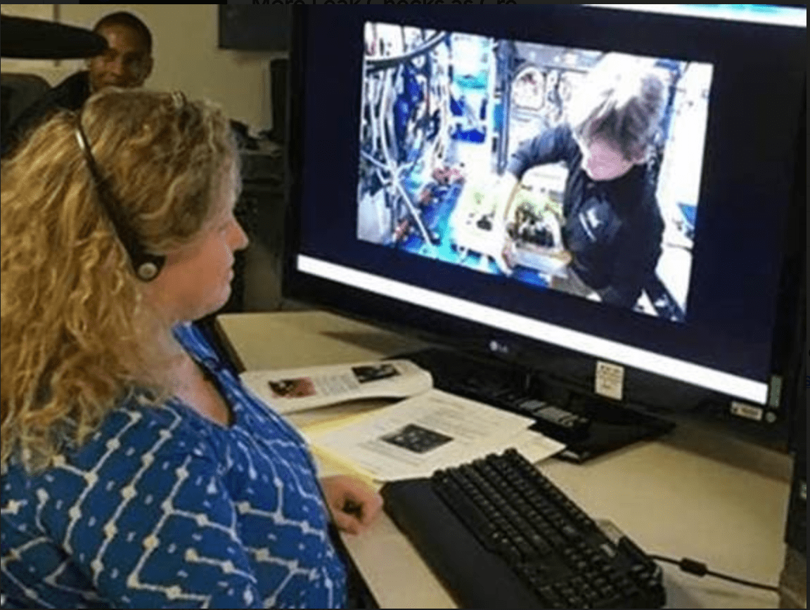
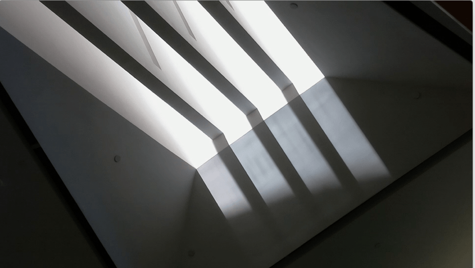
Wooster Hall on the SUNY New Paltz campus was completely remodeled recently, and a neat new feature is an alignment of the skylight over the main stairway such that the bottom of the stairs is lit up at exactly solar noon on the Equinox  (both spring and fall).

This spring when I observed this I was inspired, on the fly, to create a time-lapse video of the event, using just my hand-held phone.   You can see the video here.

Making the time-lapse video from the still images was a fun little exercise in Python programming, and the purpose of this post is to show how I did it.   I need to start out by saying that this is all really crude compared to what one can do now with time-lapse photography, but it was what I was able to do with little background or training, so I wanted to at least record what I learned.

One of the challenges to deal with is that the images were not captured at regular intervals, since I was taking them by hand with my phone.   I tried to space them out about every minute, but sometimes it took longer (like when someone was in the way) and sometimes I took them more frequently (as we got closer to solar noon).   Even so, I wanted to make the video flow as smoothly as possible by adjusting the time between frames accordingly.    That lead me to choose to make an animated GIF instead of some other format, because an Animated GIF can have different time delays for different images, whereas most video has a uniform spacing between frames.

My previous experience making an animated GIF was using the command line convert tool from Image Magick, but even that assumes a standard frame rate and does not make it easy to change the delays individually for different frames.   Still, I knew that the time of each image was recorded in the JPG file, so in principle I could use that to adjust the time between frames, if I read that information programatically.   That lead me to choose to write a Python script to do the job.   And then looking at what was available in Python, I chose to use PIL, the Python Image Library.

The way it works, overall, is that you read in all the images into a list, then save the first image as a GIF, and at the same time tell it to append all the other images, with an array of different time durations to show each image.   For animated GIFs the time to show each frame is in hundredths of a second, so I simply scale down the time interval between when the pictures were taken to an appropriate amount in hundredths of a second.

I also needed to do some processing for each image, before it was added to the animation.
Because I held the phone horizontally (landscape) but the JPG files default to “up” being portrait mode, I had to rotate each image by 90 degrees.   I also wanted to scale down the size of the image to make a smaller animated GIF appropriate for a web page, rather than a full sized video.

To get started I imported PIL and set up some empty arrays to hold the images, the durations (time between frames), and the names of the original image files.

from PIL import Image

images = []
durations = []
prev_time = datetime.now()

The current time is saved in prev_time to start the process of computing the time between successive photos. At this point I just needed a value which is both a ‘dateime’ object and somehow signals that it’s not a part of the sequence of times, which this does by being so much later than the first image.

Before reading in images, I needed an ordered list of the file names.  The file names are simply IMG_2921.JPG up to IMG_2821.JPG, in order.   I used the os module and made sure that the list was properly sorted:

import os

# Get a list of .JPG files
filenames = []

for file in os.listdir('.'):
    name, ext = os.path.splitext(file)
    # Only files, only .JPG files
    if os.path.isfile(file) and ext == ".JPG":
        filenames.append(file)
print "Found ", len(N), "image files.  "

filenames.sort()

With this list I was able to use PIL to read in each image file, rotate the image, resize the image, and then save the image in a list:

for file in filenames:
    img =  Image.open(file)
    rotimg = img.rotate(-90,expand=1)
    newsize = ( int(rotimg.size[0]/scale), int(rotimg.size[1]/scale) )
    frame = rotimg.resize(newsize)
    images.append(frame)

I set scale to 5.0 to reduce the size to 1/5 the original.

After saving each frame in the animation, I get the timestamp from the EXIF data in the original image, which just happens to be element 36867 of the EXIF property array. (You can look this up — I certainly had to). From this I computed the time duration for each frame, in hundredths of a second:

    # Duration of frame comes from actual time difference between photos

    exif = img._getexif()         # JPEG photo metadata (EXIF)
    datestamp = exif[36867]       # date/time the photo was taken
    img_time = datetime.strptime(datestamp,"%Y:%m:%d %H:%M:%S") # parse datestamp
    deltat = img_time - prev_time # difference as "timedelta" objects
    dt = deltat.total_seconds()   # difference in seconds (or fraction of)
    if dt < 0:                    # ignore the first one, it's bogus
        durations.append(dt*100.0/speedup) # GIF duration is in 100ths of second
    prev_time = img_time          # Save timestamp for next iteration

In Python, differences between ‘datetime’ objects are ‘timedelta’ objects1 and then we convert that to a float value in seconds, called dt, and rescale that to hundredths of a second. The scale factor speedup was set to a value of 30.0 to get a reasonable speed for the animation.

Notice that the duration of the frame is not saved for the first frame. That means that for the 99 images in the collection, there are only 98 durations (and of course they are all different). This turns out to be almost what is needed for the next step, putting all the frames together into the animation.

After this loop over all frames, the rotated and scaled images are in the list named images, the duration for each frame is in the list durations, and it’s time to put them all together. The way this is done is to write one frame image, and then tell PIL to append to it the list of the other images, with the list of durations.

print "Writing the movie..."
first = images.pop(0)
durations.append(100)     # pause 1 second at end of loop
print len(images), len(durations)
first.save("WoosterMovie.gif",save_all=True,
                              append_images=images,duration=durations,loop=47)

With 99 images in the list, the first is put into the variable first (and removed from the images list, which now has 98 elements. Meanwhile, I had to add another element to the end of the durations list, so now there are 99 durations. That makes some sense, because there are 99 images overall, but the mis-match between the length of the images list and the durations list was very confusing to me, and is probably the most important reason for writing this posting. Which is why I even printed the lengths to verify them when I finally got it figured out. But as you can see from the comment, it also means I could control the length of the pause at the end of the animation before it repeated. Also as you can see, you “save” the first image, and then pass the other images and durations as parameters, which seemed kinda weird at first, but that’s how the API works, so that’s how you do it. Hopefully this working example is useful to someone else, or at least to me in the future when I forget all this.

References

  1. Python Documentation, 8.1.4. datetime Objects https://docs.python.org/2/library/datetime.html#datetime-objects

Vernal Equinox in Wooster Hall

Vernal Equinox in Wooster Hall

The newly updated Wooster Hall has a neat feature at the bottom of the staircase between the first and second floors.  Above that stair  there is a large skylight with 4 windows, and at the bottom of the stairs there are markings on the floor that show where the shadows between those windows will be at solar noon on the Vernal Equinox (see the image above).

I was able to observe this phenomenon in some detail on Tuesday, 19 March 2018 (which was actually the day before the equinox, but the weather was expected to be cloudy the next day, and indeed it was). When I arrived I found a nice corner to observe from, and although I had not planned to do so ahead of time, I ended up taking a picture just about every minute (and more frequently right around solar noon) for an hour or so. After a little research I was able to write a Python script to put the images together in the following animated GIF  (keep your eyes on the shafts of sunlight moving across the floor):

The speed  is a little rough — I was aiming for one second of animation for one minute of real time but apparently I still need to make some adjustments, and even then it might depend on which browser you are using.

It was a little tricky to do this right, because I was not able to take the photos at regular intervals, and so the duration of each frame in the animation had to be computed from the time of the photo, which was extracted from the EXIF metadata. In case it is of some interest, the details of how I created this animations are in my next post: “Vernal Equinox in Wooster Hall: Irregular Interval Time-Lapse Animation

Skip to toolbar