You will learn how to solder by hands-on experience building some simple electronic circuits.
Step 1: LED + R = Light
A Light Emitting Diode (LED) usually needs a resistor in series to limit the current. Solder a resistor onto one of the leads of an LED. Connect it to a coin cell to make light, and to discover the color of your own LED. Celebrate and rejoice, for you have joined metal to metal! You can also try out heat shrinkable tubing.
This seems like a simple first step, but you’ll learn a lot that you need to know to be successful at soldering. When you start, you’ll want to “tin” the tip so that the solder will spread over it instead of bunching up into droplets. You always need to keep your soldering iron tip clean, and you can do that with either a damp sponge or brass wool. You should try both. It is important to heat the work to the temperature needed so that the solder melts onto the work and flows. Melting the solder on the tip first and then trying to transfer it to the work can result in a poor “cold” solder joint.
Step 2: PCB + Switch + Coin Cell

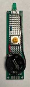
Many electronic circuits are assembled using Printed Circuit Boards (PCB’s). The components are soldered into holes in the board, and these are connected either by traces (metal strips running over the board) or by wires. This step introduces you to PCB’s and circuit layout. In this step, however, the PCB’s are “perforated” circuit boards, which have holes to hold the components, but no pre-printed traces. Instead, we will add wires to connect all the components together to complete the electric circuit.
In general, one side of the PCB is the “component” side, and the other side is the “connection” side. We don’t have to do it that way with the perforated board, but it’s still a good convention to follow, at least at first.
When you solder the battery holder to one end of the board you should try leave a row of holes below it, so that you have space for the long black wire. The battery holder should be angled diagonally so that the positive contact is on the left side of the board, where it meets the red wire. (Add the wires last – first the black wire, then the red).
Be careful with the switch, because it can have two orientations. The leads should be on the long side of the PCB, not the “top” and “bottom” in the picture. If you want to be sure, test the switch with a multimeter.
When you add the LED it can help if you spread the leads apart so that there are two empty holes between them when they are soldered. Remember, the longer lead is positive, so it should be on the left side, to join with the red wire (via the resistor and switch). The shorter negative lead joins with the black wire to return the current to the negative side of the coin cell.
To pass this step, your circuit has to work, and your instructor must inspect your joints. Use it as a wand, or a sonic screwdriver, or sew it into your necktie! Clicking the tactile switch can be very satisfying.
Step 3: Desoldering
Sometimes you make mistakes. Sometimes you make improvements. It is important to be able to undo your soldering, either to fix a problem or to make a change. Thus you need to learn “desoldering.”
An LED usually needs a resistor to limit the current through it, but as it turns out our coin cells have a high internal resistance, so you actually don’t need the resistor in the PCB you soldered in Step 2. For Step 3 you remove the resistor and replace it with a wire. Easy. One end of the wire should be removed using a solder sucker, while the other end should be removed using solder wick. Which one did you like best (and why)? In the original kit the wires were cut and stripped, but the new wire you will install is not stripped, so you will get to learn how to use wire strippers.
And since the resistor you removed is not needed, more current can flow through the LED, and you should see that it is brighter. That’s an improvment.
Step 4: Build a Kit
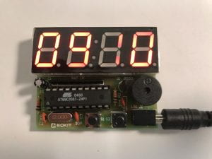
Now you just need some experience with a wider range of components, including transistors, which have 3 leads, and integrated circuits, which have many more than that. Some components with only 2 leads have to be put in place with a certain orientation (“polarity”)– not just LED’s but also electrolytic capacitors and buzzers. To finish the 4-step process you must build something from a kit that includes all of these.

So far the approved list of kits is:
- HiLetgo 0.56 Inch 4 Bit Red Digital Tube Electronic Clock DIY Kit Clock
- DAOKI C51 4 Bits Digital LED Electronic Clock Production Suite DIY Kit
More kits will be added in the future. If you have something you think will fit the requirements, please suggest it to the instructor.
Step 5: Keep on Building
Wait a minute… the title says there are 4 steps. That’s actually right; the first four steps teach you the basics, and then all you have to do is keep on building in order to get better and to refine your skills. Go forth and find new projects to build. Listed below is a partial list of possibilities, which will grow from time to time. Suggestions for additions are welcomed.
