Microsoft Teams is a collaboration app that provides text, video and audio collaboration tools with shared files and calendars. The diagram shows how it is linked to Microsoft Outlook, OneDrive, and SharePoint. Those connections are described here, along with instructions on how to link files from SharePoint into your personal OneDrive folder.
Microsoft Teams is a computer application for group collaboration, mainly aimed at businesses, but also used in higher education. But what is it really? The first example I saw was the chat feature, so I assumed it was something like Slack or Discord. But it also has video conferencing, so maybe it’s like Zoom or WebEx (though Slack and Discord now also support chat). But since it is Microsoft it also has a calendar and can connect to files on SharePoint and OneDrive. Teams is a lot of things in one, and after I started seeing those various parts linked together I though of the parable of the blind men and the elephant,1 , where each man described the elephant differently because they only had contact with one or another part. But what I’ve come to realize is that Microsoft Teams is actually Frankenstein’s Monster.
Figure 1: Which one was the monster?
What I mean by this is that Teams is really like a bunch of existing body parts sewn together and brought to life. Even so, we now have Microsoft tools here at SUNY New Paltz — our cloud storage is SharePoint and OneDrive, our Email and Calendar services are provided by Outlook, and now we have group chat and direct messaging via Teams. Microsoft has sewn them all together, and we have to live with the Monster and learn to use it as best we can.
So here are my observations and tips on how to get along with Teams, including how to create a link from your personal OneDrive folder to files stored in SharePoint.
Overview
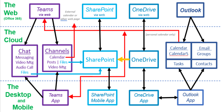
First, to really understand the whole thing I had to map out the connections between the various components, which resulted in Figure 2:
Figure 2: Microsoft Teams and how it is connected to SharePoint, OneDrive, and Outlook.
(I should mention that there are additional connections that are not shown in the diagram to make it a little easier to understand.)
One of the key features of Teams is that all the data lives on servers, “in the cloud,” and can be accessed either by native desktop apps, or apps on mobile devices, or via a web browser from wherever you happen to be. That’s shown by the horizontal layers separated by dashed lines.
The colors help identify the functions that are performed by various separate apps in the Microsoft toolkit. The dark blue boxes on the right represent Outlook, which handles email, calendars, task lists, and contact lists. The purple on the left shows the functionality of the Teams app, which provides group chat as team “channels” as well as direct messaging (DM’s) via “chat,” either with one person or smaller groups. A Channel is a subset of a Team. The Teams apps also provide video conferencing either within a Channel or within a Chat, as well as audio-only calling between individuals.2
In the middle we have cloud file storage, with SharePoint in light blue and OneDrive in a slightly darker blue. What’s the difference? As someone once explained to me,3 “SHAREpoint is for sharing, while ONEdrive is for one person.” In other words, OneDrive is for personal file storage, while SharePoint is for shared group files. SharePoint files can be accessed via the web or via a mobile app, but there is no desktop app. OneDrive files can be accessed via the web, via a mobile app, and via a desktop app which adds a folder to your computer as if the files were on an extra hard drive connected to your computer. By default, SharePoint files cannot be accessed from the desktop (but see below on how to add the “golden spike”).
Interconnections
Now we can explain the relationships shown by the arrows. As you might expect, the apps on the web, desktop, or mobile can be used to access their corresponding data in the cloud. Those are represented by the black arrows. But there are also connections between them. The blue arrows show that both Chats and Channels in Teams can access and store files in SharePoint (but not OneDrive).
The red arrows show calendars. In Teams you can access your own personal calendar, though apparently not any other calendars in Outlook that you might have created or manage.4 It’s also possible to create a calendar for a Channel in a Team, but this calendar is not related to any calendar in Outlook. It’s possible to share calendars between Teams and Outlook by sharing links to them just as you would share a calendar with anybody else by sending them a link, but there are no automatic connections, except for your personal calendar.
There are some other connections between the main components which are not shown in the diagram, lest it become overly complicated (as if that has not happened already). In Outlook it is possible to have a Group of people who share a common calendar and are all on the same email list, and an Outlook Group can share files in SharePoint in what is called a Site. An Outlook Group can have a Team, and for this team each Channel has a folder in SharePoint.
Also not shown in the diagram are relationships to other Microsoft tools, such as Bookings and Forms.5,6 Those could be the topic of other articles (but not by me).
The Golden Spike
The most important arrow is the small one in gold joining OneDrive to SharePoint. It is not there by default, you have to create it. And if you like using OneDrive on the desktop, then you will want to create it. As you can see from the diagram, you can access both OneDrive and SharePoint via the web, and the same is true for mobile — using separate apps. On the Desktop, you can only access your own files via OneDrive. On a desktop or laptop computer running the OneDrive app your files show up as just another folder that you can navigate like any other set of folder using the File Explorer (in Windows) or the Finder (on a Mac). It essentially extends your hard drive into the cloud. But there is nothing comparable for SharePoint — except that there is, once you create that golden link between the two. It’s like the golden spike that joined the east coast and west coast by rail so many years ago.7
All you have to do is create a link from a SharePoint directory to your own files in OneDrive, and you can then navigate to the files in SharePoint as if they are another folder on your computer, just like OneDrive. You can only create this link from the web, but once you do then it works for the Desktop and Mobile apps. SharePoint files then become available as folders on your computer just like OneDrive files.8
Here’s what you need to do to create the link:
Log in to SharePoint and navigate to the top level folder you wish to access via OneDrive:
One way to do this is to open Office 365 as you do to read email, then click on the “App Launcher” in the upper left corner (the icon looks like a waffle) and select SharePoint. In the stack of icons along the left side of the page select the “globe” icon for “My Sites” and then select the Site you wish to link to. Then select “Documents” in the left side menu.
Navigate to the folder you wish to link to. This could be the top-level directory of folders, or it could be one of the folders under it, but keep in mind that once you link to a folder, you cannot make another link further down in the directory hierarchy, or further up. You only get one shot.
At the top of the listing of the folder you wish to link to are a set of functions such as “Upload” and “Share” and “Copy link,” and among those is one labeled “Add Shortcut to OneDrive”. But since it is one of the latter ones it might not be visible, in which case you can use the “…” icon to show the full list of options. Select that one.
The new link to this SharePoint folder will now appear in your top-level OneDrive folder. You can move it anywhere you want it within OneDrive, either by dragging it in the desktop File Explorer (or the Finder on Mac) or using the web version of OneDrive (which you can get to via the “waffle” icon for the App launcher and then selecting “my files”). Just make sure you don’t have two such links in the same directory tree, one above the other.
Figure 3. Boris Grishenko (Alan Cumming) celebrates his spike (from the 1995 movie “GoldenEye“).
Congratulations, you have just driven the Golden Spike and connected files shared on SharePoint to your personal set of files in OneDrive, and now you can get to those SharePoint files using OneDrive. Easy, eh? Go ahead, celebrate!
Teams Technical Tips
At one point after using Teams for a while I found that I was not able to access files that are a part of a Teams Channel. I was able to trace the problem to my cookie settings. By default, I don’t allow third-party cookies for security reasons, though that can sometimes cause problems with a site (for example, see Starfish Requires Third Party Cookies). Since the files are actually stored in SharePoint, the problem went away once I allowed third-party cookies from sunynp.sharepoint.com. In general it is a good idea to block third-party cookies, but then allow them from sites you trust when they are needed to make something useful functional.
But as far as I can tell, not with the whole teams or with a smaller group, but I suppose you could turn off your video. Maybe I’ve missed how to do a voice “teleconference” or maybe Microsoft wants to do away with those. ↩
One consequence of this is that you don’t need the separate SharePoint mobile app, since you can access all your OneDrive and SharePoint files using the OneDrive mobile app, and you don’t ↩
It is possible to use Adobe Acrobat Reader to “sign” documents. There are actually several levels of both security and complexity, so depending on what you want to do you can either choose the easiest, or the most secure (well, at least more secure). Here are the options:
Add an image of your hand-written signature (easiest, but least secure).
Add a digital signature using a self-signed certificate (more secure)
Add a digital signature using a self-signed certificate and an image of your handwritten signature (fancy!)
Add a digital signature using a certificate signed by a Certificate Authority (even more secure)
So Many Options
This topic can be confusing because an “on-line” signature can mean any of these, and each one is different from the others:
Option 1 is the easiest, and it’s basically a (less secure 1) replacement for the steps of a) printing something out, b) signing it with a pen, and then c) scanning it to send to someone else. The idea is that you load a photo of your personal signature into Acrobat Reader (or you create a signature with the mouse — but who can do that?) and then Acrobat Reader can overlay this signature onto your document. But this option is not the most secure, because after all, if you can add an image of a signature, so can someone else.
Option 2 adds a digital signature to the document, which is more secure. To set this up you create a “certificate” file, which is encoded by a password. (Adobe Reader helps you do this.) Whenever you want to sign a document you will simply type that secret password to add the signature. This is more secure than option 1, with not much extra work to set up at the beginning, so this is probably what you want to do. It’s still possible for someone to spoof a signature by just creating a digital signature with your name on it, but it won’t match the digital signature you usually use, so it will be possible to spot a forgery if someone checks it carefully — and Acrobat Reader can check signatures automatically. It can also show a warning if the document has been altered after it has been signed.
Option 3 is an extension of Option 2 which lets you add an image to your handwritten signature. The image could be anything, but the nice thing about this choice is that you can use an image of your hand-written signature so that it actually looks like you signed the document even to people who don’t know about digital signatures.
Option 4 adds extra authentication. Instead of creating a “self-signed” certificate (that’s what is done in Option 2) the certificate you use to sign is itself signed by a higher-level certificate, from what’s called a Certificate Authority (CA). This is how certificates work for secure web pages (those that use https rather than http) to avoid spoofing. This option is not currently available at SUNY New Paltz, and for everyday work documents that’s (probably) okay.
So there are really two options, and in Adobe Acrobat you choose them with two different tools:
To “sign” a document with an image of your handwritten signature, select the Tools tab and then open “Fill & Sign“. [Details Below]
To sign the document digitally using a certificate, select the Tools tab and then open “Certificates” [Details Below]
Either way, there is some initial set-up you have to go through the first time you sign document, and it’s a little bit different for each method. But after that the process is fairly quick and easy whenever you need to sign a document, no matter which one you choose.
1. Adding a Signature Image
A digital signature is more secure, but if you really just want to add an image of your hand-written signature then here is how to do it:
Write your signature on a blank piece of paper, take a picture of it and save it as either a JPEG or PNG file. You’ll just have to add this image to Acrobat Reader the first time you sign something, and after that it will remember the image.
Open a PDF document you wish to sign using Acrobat Reader, select the “Tools” tab and click on “Fill and Sign“.
Along the top of your document you will see the Fill & Sign toolbar. Select “Sign Yourself”. (You can also change the color of your signature here: click on the circle to select a pen color.)
If you have previously loaded an image of your signature, it will be shown and you can just select it. If you have not previously added a signature image then select “Add Signature”, and then..
At the top of the window that pops up, select “Image”
Use the file chooser to select the image containing your handwritten signature
Press “Apply”
Once you have a signature image loaded, click on it to select it.
The image of your signature will appear over the document and you will already be dragging it around with the mouse. Place it where you want to add the signature. You can use the dot at the lower right corner to resize it, or you can use the smaller or larger “A” buttons to shrink or enlarge the image. You can also click on the image to drag it around for better positioning.
Click anywhere away from the signature image to leave it in place. Click back on the signature image to modify the position or size. Once you save the document you will no longer be able to adjust the size or position of the signature.
(Note that on a Mac you can also do the same thing using the Preview app. While viewing the document you want to “sign” pull down Tools → Annotate → Signature. To load an image of your signature, click on “Manage Signatures…” and follow the directions. If you have already loaded an image then you can just click on it and it will appear overlaying your document. Drag it into place and resize it. )
2. Signing with a Certificate
Signing with a certificate is a true “digital” signature. Your certificate is a public key, signed by a private key (or by a Certificate Authority – but that option is currently not available at SUNY New Paltz), and used to create a digital signature. Adobe Acrobat will do all the heavy lifting to create your certificate (and private key) – all you have to do is answer some simple questions.
When you want to sign a document using a digital certificate, click on the Tools tab and open “Certificates,” then click on the “Digitally Sign” button above the document.
Use your mouse to drag out a rectangle where you wish to place the signature. (When you first start signing documents you will be prompted to do this, but you can turn that prompt off. If you turn the prompt off but you don’t sign things often then you might get stuck waiting at this point.)
If you have previously created a signing certificate (a “Digital ID”) then it will be shown and you can select it. If you have not yet created a signing certificate then you will need to do that (only once), as follows:
Select “Configure Digital ID”
Select the option to “Create a new Digital ID”
Select the option to “Save to Windows Certificate Store” to make your certificate public2
Enter your Name, department, campus , and e-mail address.
You will be asked to choose the Digital ID that you want to use for signing, and there is probably only one choice (though you can create multiple Digital ID’s if you wish — see below). Simply select that ID (it’s probably already selected) and press “Continue”.
You can click the “Lock document after signing” checkbox if you want that option, but don’t do so if others need to add their signature. (If you saved your Digital ID to a file, instead of saving to the Windows Certificate Store, then you would have created a password to protect your private key, and you’ll have to enter that password now.)
Press the “Sign” button to sign the document. You will be prompted to save the file, either using the same name and overwriting the original, or in a different file.
3. Digital Signature with Image
It’s possible (though a little bit more complicated) to create a digital signature which includes an image of your handwritten signature. How cool is that? If you are willing to go through a few extra hoops, this section describes how to do it
The way this works is that in Acrobat Reader your digital signature has the option to include an image, which is referred to by Acrobat Reader as a “logo.” And since it is Adobe, your “logo” has to be a PDF file — it can’t be a JPEG or PNG image. So you will need an image of your hand-written signature stored as a PDF file, however you manage to do that. One easy way is to use the OneDrive app on your phone to scan your handwritten signature as a document. On a Mac you can open the image with the Preview app and save as a PDF.
Once you have the PDF file on your computer, put it in the folder
where “<username>” is your own username on the computer. The “AppData” folder is hidden by default, so to view it you may have to select the View tab when looking at your home directory and check the box for “Hidden items”. This is where Adobe Acrobat stores PKI3 resources, so putting files here will make them more easily available to Acrobat Reader.
Since this is just an add-on to a regular digital signature, you should first create a “Digital ID” as described above under Signing with a Certificate. With this in place, start out to sign a document using “Digitally Sign” (you’ll have to highlight a rectangle even if you don’t intent to complete the process). Select the Digital ID and press “Continue”. Before you press the “Sign” button, press “Create” at the top of the pop-up. Now you will be able to customize the signature block, including adding the “logo” image. Above the display of how the signature will look, select “Image,” and then below the display click on “Browse”. You should see a list of files in the “Security” folder shown in the AppData path above, and this should include the PDF file of your hand-written image. Select it and press “Open”. Then press “Save” to save this customized signature block.
Now whenever you sign a document with this Digital ID you simply have to select the rectangle for the signature block and press “Sign” to add both a true digital signature and an image of your hand-written signature.
4. Certified Signatures and Certificate Authorities
Before describing how this works, it’s important to know that we don’t use this at SUNY New Paltz, or (as far as I can tell) SUNY in general. So this description is included only for completeness, and to point out that there is a more secure way to do digital signatures, which should be the goal.
A certified digital signature is sort of like having your signature witnessed by a Notary Public. The notary also signs and marks the document to insure that the person claiming to be the right person was the one who signed the document. In the digital world a Certificate Authority (CA) will create a digital signature of a person’s digital signing certificate, and this helps insure that the digital signature was not spoofed. A document could be signed by someone claiming to be you, but only your digital signature will include the certificate from the CA that verifies that it is legitimate.
Right now at SUNY New Paltz our digital signatures are “self-signed,” which means that there is no higher level of verification. That seems fine for now, but in the future you might expect digital signatures to be backed up with a SUNY Certificate Authority.
Managing Digital ID’s
It’s possible to have more than one Digital ID, and to delete one you don’t want to use, or export one that you want to use on another machine. To do any of this pull down the Edit menu to Preferences → Signatures and select “Identities & Trusted Certificates“.
To delete a Digital ID select it (highlight it) and then click on “Remove ID”
To export a Digital ID highlight it and click on “Export” . You can save the certificate to a file or have it emailed to someone, and you can save it in several PKI formats.
Notes and References
Option 1 is slightly less secure than actually signing a document and scanning it, because anybody who can get an image of your personal signature can do the same thing ↩
This makes your certificate public, so that others can verify your digital signature, but it does not publish your private key. The “Certificate Store” is “storage” for certificates, not a palace to buy them. Your private key is (presumably) encrypted with your Windows Live credentials. As a result, you don’t have to type in your password every time you sign a document, assuming you are logged in with your New Paltz ID. ↩
“PKI” is Public Key Infrastructure, the technology that underlies digital signatures and public key encryption. ↩
An on-line form can be an easy way to collect data from students during a lab or class, and with the data automatically loaded into a spreadsheet it can then be straighforward to work with the data immediately. Google Forms is one way to do this, but since SUNY New Palz is moving to the Microsoft Office 365 suite of tools we need to know how to do this in Office 365. This article gives you enough information to get started, and those who are already familiar with Google Forms will see a lot of similarity. This kind of form can also be used to give a quiz or perform a survey (though there may be better tools for that).
Figure 1: example of a QR code leading to a data input form.
It’s worth noting that students can even enter data from a mobile device once you give them the link to the form, and there are several ways to easily distribute the link, including displaying a QR code (see Figure 1). This can make collecting data especially easy, as long as you make the form available to anyone (not requiring authentication). Keep in mind, though, that not all of your students may have a phone that can read QR codes. Making the link available in several ways may be the most effective strategy.
It’s also worth noting that there is a tricky bug in Microsoft Forms that causes problems when working with numerical data (see the section Working with Data below). Although there is a workaround, I suggest using Google Forms if you can instead of Microsoft Forms, at least until this bug is fixed.
Creating a Form
Open Office 365 (for example, by going to www.newpaltz.edu and pulling down the “Resources” menu at the upper right) which will start you in the Outlook email App. Click on the App Menu icon in the upper left corner (some say it looks like a waffle):
Figure 2. Office 365 App Menu (the “waffle”).
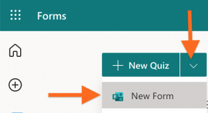
When the App Menu opens up, click on the icon for the “Forms” App:
Figure 3: Click on the “Forms” icon.
The page that opens up will show you any forms you have already created. To create a new form, click on the downward chevron (“v”) next to “+ New Quiz” to reveal the menu item to create a new data input form. (A Quiz, in contrast, lets you add the correct answers to the questions and have the quiz scored for you automatically.)
Figure 4: How to create a new form.
A new page opens to let you edit the new form. First, enter a title for the form, and a description or instructions to be displayed under the title:
Figure 5: Form title and description/instructions.
Then press the “+ Add New” button to create a new question. At the bottom right of the new question are three dots, “…” to open a menu of options. Adding a subtitle lets you add more text to the question (such as specifying the units or giving a reminder about something):
Figure 6: Adding a subtitle, and requiring a numerical
Selecting “Restriction” lets you require that the response be a number (or more specific restrictions on the value of the number). But see the section Working with the Data below for a caveat.
Use the “+ Add new” button to add as many questions as you need.
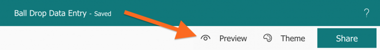
You can test your form with the “Preview” button at the top of the screen.
Figure 7: Preview button to try out your form.
(Note that you can also use the “Theme” link next to “Preview” to apply a pre-made design theme to your form, or to apply your own customization.)
To exit the preview there is a “<- Back” button at the top of the page.
Viewing the Data
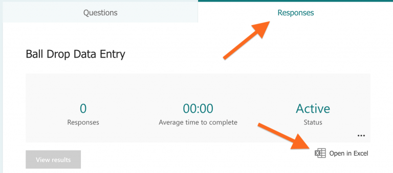
As you test your form the data you enter will show up in a spreadsheet. To view the data switch from the Questions tab above the form to the Responses tab:
Figure 8: Responses tab and link to the data.
Click on the “Open in Excel” link to view and work with your collected data using Microsoft Excel. If you are logged in to Office 365 in your browser then Excel will open in a browser tab or window. If not, the file will be downloaded to your computer and opened with Excel.
Once you open the spreadsheet you will see that there are columns which show the time the respondent began filling out the form, the time they pressed the submit button, and their email address and name if they were authenticated. If you don’t want this extra information visible, if only because it clutters up the screen while you are working with the data, you can select a column or columns, right-click on the top (or control-click on a Mac) and select “Hide Columns.” If you are going to share the data file with students and don’t want them to have the hidden data then you will need to actually delete the columns, not just hide them.
Publishing the Form
To collect data from students (or anyone else) you need to give them a link to the form. To do so, click on the “Share” button at the top of the form page, just to the right of the “Preview” and “Theme” links (see Figure 7). A tool will open from the right of the screen:
Figure 10: Menu to share the form via a web link (URL).
First, select who can view the form. If you select “Anyone can respond” then students won’t have to authenticate to fill out the form, and in fact it will be very easy for them to answer most questions using their phone. (The exception is a question requiring a long answer, though some students can type on a phone quite fast with their thumbs.) To account for this, the first question on your form can be to ask for their name or nickname. And if you choose not to ask their name as a question on the form, and they have not authenticated, then all responses will be anonymous, which may be desirable in some cases.
Check the box for a short URL if you will share the link with your class by writing it on the white board or sharing it via a projector for them to type in. Press the “Copy” button to store the link in your clipboard, and then paste it into a message you send to your students, either by email, or by adding a link to your Blackboard page, or whatever works easiest for you and your students.
The four circular buttons at the bottom of Figure 9 let you select one of four different ways to distribute the link to the Form. The default, shown in Figure 9, is to let you copy the URL and paste it somewhere else. The second lets you create a QR code for the link, which you could display in class or on Blackboard on in a document, and students can then scan it with a phone to go to the Form. The third button will create HTML code that can be embedded into a web page. The last one lets you sent the link via e-mail,
In any case, following that link will take your students to a page (unless they have to authenticate first) where they can answer the questions on the form.
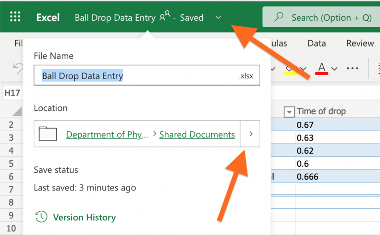
Moving the Data File
By default, the data file associated with a form is (or seems to be) stored in the Shared Documents folder for your Department or Team. That’s fine, especially if the form is shared between several instructors in the department. But if you want to move the file to your own file storage area then the easiest way to do so is to open the data file and click on the downward chevron “v” next to the word “Saved” right after the name of the file, which will open a menu to rename and/or move the file:
Figure 9: menu to rename and/or move the data file.
Under “Location” you will see where the data file currently lives, and you can press the “>” button to change the name of the file, or move the file to a new location (or both). For example, you would probably want to move it to a folder under “My Files” for the class for which you are collecting the data.
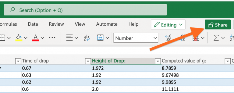
Sharing the Data File
Since the data are stored in an Excel spreadsheet in OneDrive you can share it the same way you would share any document from OneDrive. When you share it, you can specify if the person you are sharing with can edit the file, or only read it. The easiest way to share the spreadsheet is to open the file and click on “Share” at the top of the page:
Figure 11: How to share the spreadsheet with someone else.
You can either share by entering the email of the person you wish to share with, or you can copy a link and then paste it into a message you send to them by whatever means you find convenient.
One interesting way to use this is to have one instructor create the form and then share it to another instructor to collect and view the data from that instructor’s class. If editing permission is granted then the second instructor can use the spreadsheet in class just as if they had created it. At the end of the class the spreadsheet can be cleared (perhaps after copying it) to prepare for the subsequent class.
Working with the Data
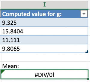
Once you have collected the data into a spreadsheet you can do just about anything you could do with data from any source using a spreadsheet, with one big exception: numerical data are not actually numerical.
There is a tricky bug in Microsoft Forms where even if you specify that the value to be entered into the form must be a number, it is recorded in the spreadsheet as a character string. This isn’t obvious, because the values in the columns of the spreadsheet will look like numbers. You can only see that they are not numbers if you click on a cell and then inspect the contents in the Formula bar near the top of the page; the value will have an apostrophe in front of it, which tells Excel to treat it as text rather than as a number. (This is how you can keep a leading zero on a zip code.)
The problem with this is that it gets in the way of applying statistical or trig functions to the data. Figure 12 shows what should be a valid operation in Excel, but Figure 13 shows the result when you press Enter.
Figure 12: Taking the mean value of a column of values using the AVERAGE() function.
Figure 13: What happens when you press Enter.
The function acts as if it had received no numerical data, because the values in the column above are actually text, not numbers.
There are several workarounds to this. Perhaps the easiest is to multiply the range in the function call by one, by inserting “*1” in the range. Doing simple multiplication on the values in the column still works and produces numbers, which can then be used by a function. So in place of the formula in Figure 12 one would write:
Figure 14: Multiplying the range passed to the function by 1 is a simple workaround.
Another option is to try to remove the apostrophes from all the data, as described here1 and here,2 but that can be a little more difficult to manage on the fly during a class.
This bug has apparently been in Microsoft Forms since at least the Fall of 2019.3 Until Microsoft fixes this, I see nothing wrong — when demonstrating this in front of a class — with explaining that the extra “*1” is needed because Microsoft has not yet fixed their crappy code after several years.4 One could also mention that this is not a problem with Google Forms.
There is another bug you may want to be aware of, if you will reuse the form for more than one class or class section. The button to “Delete all responses” does not work:
Figure 15: Button to reset the form by deleting all responses (but as of Spring 2022 this does not work).
It will reset the count of responses, but it does not delete data from the spreadsheet. If you really want to reset the form by deleting old data then you will have to go into the spreadsheet and delete the previous data manually.
This page describes how to configure the network interfaces for a Raspbery Pi running as a Wi-Fi Access Point (AP). This is just one step in a larger list of instructions, which can be found on the page Raspberry Pi Wifi Access Point. The instructions here do not include the routing, which is covered later.
We need to configure two networks, the “local” network managed by hostapd to be a Wi-Fi Access Point (AP), and the “upstream” network connection to the Internet. The upstream network can be wired or Wi-Fi, and it could use a fixed IP address, or it could be a DHCP client, so there are lots of possible variations. We will use wlan0 for the Wi-Fi Access Point, since we will always have that on Wi-Fi, and use wlan1 if the upstream network connection is also via Wi-Fi.
Local Area Network (LAN) for the Access Point (AP)
The first Wi-Fi adapter, called wlan0, will be used for the Wi-Fi Access Point (the local network). It’s best to use the IP address range for a Private Network.1 For a small home network you can put the following (or something like it) in the file /etc/network/interface:
This configuration is for a “Class C” network, which can have up to 254 IP addresses. For a large public event or venue you will probably want to use a class B or even a Class A network.2 In that case you can use the values in Table 1 to fill in the appropriate fields in the interfaces file.
Name
Size
address
network
netmask
broadcast
gateway
Class C
254
192.168.47.1
192.168.147.0
255.255.255.0
192.168.47.255
192.168.47.1
Class B
65,534
172.16.0.1
172.16.0.0
255.240.0.0
172.16.255.255
172.16.0.0.1
Class A
16,777,214
10.0.0.1
10.0.0.0
255.0.0.0
10.255.255.255
10.0.0.1
Table 1. Private Network settings for Class C, B, and A networks. For more details on private networks see RFC 19183
Upstream Connection
There are several different ways to make the upstream connection. It can be wired or Wi-Fi, and it could have a static IP address or it could get an address and other network settings from a DHCP server.
EDITED TO HERE
We will put the configuration for each interface in a separate file in the directory to make it easier to select which upstream interface to use, and also because it allows you to be a DHCP client on the upstream link.
(If you have a static or dhcp interface in /etc/network/interfaces then the dhcp client won’t start.4) If your access point won’t act as a DHCP client (it will definitely be a server, but that is different) then you can put all the configuration into the one file /etc/network/interfaces.
First, add the following to the top level file, /etc/network/interfaces:
# wlan0 is the Access Point

allow-hotplug eth0
allow-hotplug wlan1
# Now read full interface configuration from the subdirectory
source-directory /etc/network/interfaces.d
That last line is what reads the other files in that subdirectory. I have found that it is important to use allow-hotplog for wlan0 instead of auto; When I used auto then hostapd could not find wlan0, though it was up later when I checked. Maybe the boot order is different?
The upstream connection can be either via wired ethernet, on interface eth05 or via Wi-Fi, on interface wlan1. I will describe both and you can pick one or the other to connect to the Internet. It’s even possible to have both upstream links enabled at the same time — in case one fails the other will still work. You have to decide if you use DHCP (as a client) or a static the IP address and netmask and gateway.
First, put the following in the file /etc/network/interface.d/wlan1 for the second wireless interface:
Next, add the following to /etc/network/interface.d/eth0 for the wired upstream connection:
iface eth0 inet dhcp
These are just examples – you could use a static IP address for the wired interface, or use dhcp for the upstream WiFi connection. Having an entry for an interface that does not exist won’t cause problems.
In this article I report what I’ve learned so far about the possibility of using steerable consumer home monitoring cameras (“nanny cams”) to allow students to work together on laboratory exercises, with one student in the room and one (or more?) participating using the video and audio from the camera. (~4660 words)
Introduction and Motivation
The COVID-19 pandemic caused all instruction at SUNY New Paltz to move online in March 2020, including labs. Introductory physics labs were performed by having faculty record videos showing the apparatus and the process of collecting of data, and then students analyzed the data and wrote lab reports. This lost a number of the benefits of student lab work, including both real-time interaction with the equipment and real-time interaction with other students.
Lab students work together as “lab partners” for a number of reasons. One is that equipment can be limited, especially if it is expensive. Another is that some activities require more than one set of hands. But even when these considerations don’t apply, it has long been recognized that working together with a lab partner is a valuable part of lab. Getting an experiment to work requires problem solving and troubleshooting,1 and collaboration makes this easier and more instructive. Collaborating with a lab partner can be a form of peer instruction, which has long been recognized as a useful tool for teaching physics in both labs and in lecture classes.2
If we are able to have students in the classroom in Fall 2020 they will likely be required to wear masks and to be spread out in the classroom to preserve “social distancing.” The masks won’t be a problem, but being “spread out” is in direct conflict with working together as lab partners. One potential way to have students work together but preserve distancing would be to have one student working in the classroom and another connected via video chat. A problem with using a standard video chat application is that our laptop computers have a built-in camera that only faces the front of the computer, which does not easily give a view of the equipment. We could add an additional web camera, and then the person in the room could point it at the experiment. Either way, using the computer for video would provide a static view (which admittedly is better than nothing) and would require the student in the classroom to continually adjust the camera. A clear improvement would be if the remote student could control the camera themselves to look around as the experiment is being performed. Unfortunately, cameras which can pan and tilt (and possibly zoom)3 which are compatible with common video conferencing systems like WebEx or Zoom are expensive,4 and we would need one for each lab station.
A note on terminology: At SUNY New Paltz5 the word “hybrid” is applied to a course which has an in-classroom component and an on-line component. But this is not very specific. The hybrid courses in our department implement the “flipped classroom” method, where students view content material such as recorded lectures online and then come to class for discussion and problem solving. Having some students in the classroom and others joining remotely via computer is another variation of “hybrid” but is different from a flipped classroom. I will use the term “local+remote” to specifically mean a synchronous class or activity where some students are physically in the classroom and others join via computer, all at the same time.
Home Monitoring Camera
Figure 1. YI-Cloud Dome Camera 1080P, a home camera which can pan and tilt.
A potential alternative to an expensive steerable web camera is a commercially available home monitoring camera (aka “nanny cam”). The model I chose to test, shown in Figure 1, is the “YI-Cloud Dome Camera 1080P,” which sells for about $30 per unit.6 I chose this camera simply because I had previous experience with an earlier static camera from the same company. My family has used that camera to check up on my elderly mother when she was home alone (before the pandemic). We called it the “Granny Cam.” Other common uses are to watch pets at home or to keep an eye on a baby in another room. From my prior experience with the static camera it seemed that a similar camera which is steerable would work well for connecting virtual lab partners. And contrary to the implication in the name, use of “the cloud” for storing video is not required.
Network Configuration
Setting up the camera is very easy in a home environment, but more complex on campus, where we use RADIUS authentication for the Wi-Fi network using individual usernames and passwords. The camera is designed to use WEP or WPA2 authentication (using the SSID of the Wi-Fi network and the (single) password for that network), as is common for most home routers. The camera has an RJ-45 jack so that it can be connected directly to wired Ethernet, but that only worked after the camera had been paired with my mobile phone app using Wi-Fi. Since my phone connects to our campus Wi-Fi using RADIUS but the camera cannot, this presented some difficulty.
One way to get around this difficulty is to pair the camera and mobile phone while using a different WPA2 network, and once that is done then the camera can be connected to wired ethernet. A remaining complication is that Wi-Fi won’t work if that WPA2 network is no longer available (e.g. if you paired the camera to a phone at home and then brought it into the lab). It is likely we would want to use the wired Ethernet in any case to avoid network interference and congestion from using many of these devices in one room. (But I also found a way around this; contact me for details.)
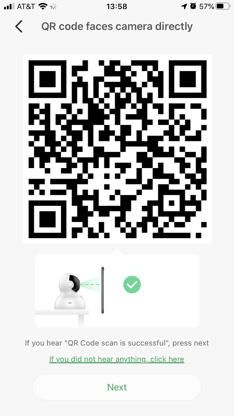
Figure 2. QR code use for pairing a camera with the mobile app
The pairing process is fairly straightforward. The camera starts in pairing mode when plugged in the first time, or after you press and hold a reset button on the back, and it gives voice prompts to indicate where it is in the process. On iOS at least you have to allow the app to obtain your location — perhaps for added security? The user enters the Wi-Fi network name (SSID) and password, which are encoded into a QR code (see Figure 2) which is displayed on the screen of the mobile device. That QR code is shown to the camera,7 which reads and decodes the QR code and uses the SSID and password to authenticate to the Wi-Fi hotspot. After only a minute or two the camera is paired to the account used on the mobile app. It can then be accessed using the manufacturer’s mobile app from any device using that same account8, and the camera can also be “shared with family” to someone using a different account (an important feature discussed further below).
Although you cannot pair the camera on wired ethernet it is possible to switch between wired ethernet and Wi-Fi. Whenever an ethernet cable is plugged in to the device it will switch to the wired connection, and when it is unplugged it will switch to Wi-Fi (if it is able to do so). I have not measured the time it takes to make these transitions
These kinds of cameras are made to allow a homeowner to see the view from the camera when they are away from home. In my lab I tested accessing the camera from off campus by turning the Wi-Fi off on my mobile phone and on an iPad and using my carrier’s mobile data network on both to verify that I could access the camera. Even though I was in the same room, the packets had to get to and from the camera by entering and leaving the campus network, and that worked fine. I later verified that I could view and control the camera when I was 10 miles from campus. There was a noticeable increase in latency when using the mobile network from a distance.
Gooseneck Mount
Placing the camera on the lab table did not give a good view of the equipment, which is also on the table, so it was necessary to lift the camera up to the eye height of a typical student. A traditional camera tripod proved to be too tall when placed on the table with legs fully retracted. The height would be easier to adjust with the tripod on the floor with legs extended, but the spread legs would then take up a lot of room that would otherwise be available to the student working at the table.
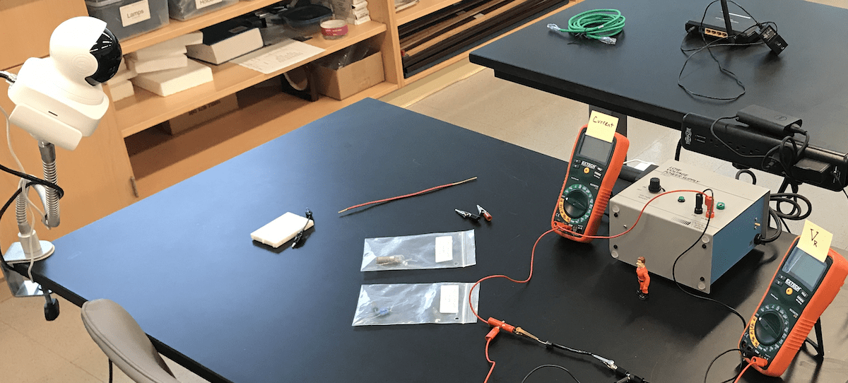
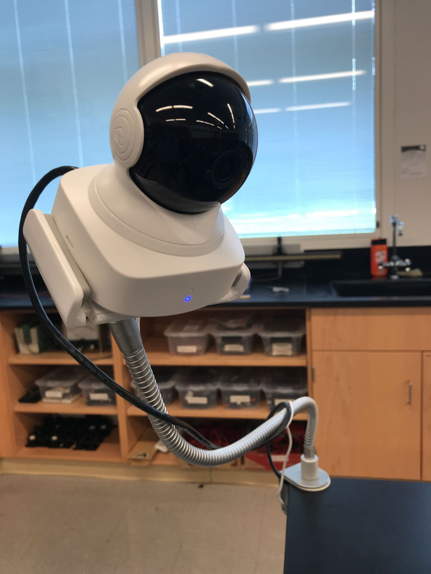
Figure 3. Home monitoring camera mounted on a gooseneck support and aimed at a typical physics experiment (for a lab dealing with Ohm’s Law).Figure 4. Home camera mounted on a gooseneck support.
So to position the camera with the right height and direction I used instead an AboveTEK Heavy Duty Aluminum Gooseneck iPad Holder,9 which clamps to the table top, has a spring clamp which holds the camera securely by the base, and can be bent into position to match the eye height of a student but without getting too much in the way of the person working at the table (see Figures 3 and 4). The camera base was tilted downward so that the remote student could tilt the view downward to look at the table. Otherwise the downward tilt angle of the camera was too limited, while the upward tilt went all the way to the ceiling (which is not useful).
We might be able to construct our own gooseneck mounts using flexible metal wiring conduit mounted on the table with bench clamps (we have plenty of those) with a custom-made 3-D printed camera mount on the end.
Audio and Controls
A mobile app is available from the manufacturer for both iOS and Android, and testing shows that the interfaces are very similar, which means that documentation and training for students would not have to be different for the two platforms.
The camera has a two-way audio feature which lets the remote observer hear audio from a microphone built into the camera, and to say something through speakers also built into the camera. There are two different modes for the remote observer to talk. A button on the screen can be used for “push-to-talk” or “intercom mode,” meaning it has to be pressed and held while talking, which would not be the best configuration for lab partners. But the settings can be changed to “hands-free mode” so that the button turns the remote observer’s microphone on continuously until pushed again to turn it off. This would be the best way for lab partners to carry on a continuing discussion throughout the experiment. The remote student would have to be given instructions on how to change this setting, since it is not the default.
Figure 5. showing the controls when the camera is first selected.
The interface for controlling the camera is easy to use, with some minor complications. The initial view is “portrait” with the steering “joystick” control prominently displayed (see Figure 5). But the view does not switch to a larger “landscape” view simply by turning the mobile device, as some might expect — one has to press the “spreading arrows” button in the lower right corner to shift to that larger view (see Figure 6). One on-screen button allows the user to turn the audio monitoring on or off (either as a toggle, or push-to-talk mode). Another lets the user take a still photo, which are saved to the camera roll on their own mobile device, and can also be saved to Google Drive or shared via email or text message. Students could use this to take a photo of the entire apparatus, or parts of it, or perhaps of just a meter reading. Another on-screen button lets the user record video from the session (again saved to their own mobile device). An example of such a video is shown in Figure 7. A student could record the whole lab, or key parts of it, and review that video later. In the expanded “landscape” view the camera steering controls are not obvious (but are also not in the way). Tapping a small icon in the upper right of the screen (see Figure 6) expands the steering controls while hiding the other audio/video controls. Tapping on the screen again will clear away all control icons. It’s all easy to use once you see it.
The steering controls are fairly responsive when one is on the same network as the camera. A student using the camera from a dorm room or other location on campus should not have any troubles steering the camera. There is a bit of a lag in the steering controls when accessing the camera from off campus. Tapping the controls and waiting to see the result leads to the desired results. There may also be an audio lag, but that has not yet been tested.
Figure 6. Camera controls, once the view is changed to the expanded (landscape) orientation.
While the camera does not have a hardware zoom feature, one can zoom in software using the familiar “unpinch” gesture of spreading two fingers on the screen. The camera has two resolution modes, “SD” and “HD”. On a good network connection the HD video works well. I have not pressed the limits to see how a poor network connection degrades the video, or measured the bandwidth requirements.
Sharing the Camera
One key feature that will make it easier to use this device for connecting virtual lab partners is that a camera can be “shared with family.” This means that the camera can be paired initially with the account of the lab manager or faculty member who runs the lab and who always maintains control of the device. The video and audio from the camera can then be shared with a student who has a different account (created using their campus e-mail address), but the student cannot accidentally modify or delete the camera, and access to the camera can be revoked once the lab exercise has been completed (if that is deemed necessary).
I will also note that each camera can be given a name, and that name can be changed in the app settings. We might, for example, change the name whenever a camera is moved to a different lab station.
Figure 7. Example of data collection, as viewed from the camera. In this case, for an experiment to study friction. Note the manufacturer’s logo watermarked on the video in the lower left corner.
History Review Feature
The camera manufacturer has a subscription cloud service for saving recorded video, but this is both optional and unnecessary for our planned use of the camera. One can insert an SD card into the camera, in which case video and audio can be recorded automatically on the camera and played back by the remote observer. This would, for example, allow the remote student to go back and review something that they missed or wanted to study in more detail. The interface for this is straightforward: a time “scrubber” is shown at the bottom of the screen, and the user can drag the scrubber back to the desired time to view the recorded video (see Figure 6). This history review feature is always available to the “owner” of the camera, but must be specifically enabled for the guest account to which the camera is shared — it’s off by default.
We will have to think about how we might use this history review feature, and whether it is worth the additional expense of an SD card for each camera. The camera works fine for real-time viewing without the SD card. With the SD card it would be possible for a student with access to a particular camera to view not just their own work with their own lab partner, but the work of previous students who used the same camera. That may or may not be desirable, or worth worrying about. An instructor who was not present for the lab period could use this feature to verify attendance and participation, or to review student work to give assistance, or to evaluate problems with the equipment or lab documentation.
Desktop Client App
It would be useful for the remote student to be able to see the view from the camera on the larger screen of a desktop or laptop computer. Until recently, this particular camera manufacturer only provided apps for mobile devices, and my own survey (possibly incomplete) of similar products suggests that this is a property of the commodity market. It is a selling point for all that they work with manufacturer-specific mobile apps, many with Amazon Alexa, but there is little or no mention of access via web or desktop computer.
Fortunately, this camera manufacturer has recently released apps for both Mac and Windows. Unfortunately, the Mac app failed to run on MacOS 10.15.4 with a pop-up warning saying it “can’t be opened because Apple cannot check it for malicious software.”10 Further testing is warranted, but this is discouraging. On Windows there is a similar warning when you go to install the software, but you still have the ability to do so. Once started, the app looks a lot like a mobile app, but still with standard Windows controls in the title bar.11
The app on Windows works to view from the camera and to listen to audio, and the controls work to steer the camera, but the intercom feature is missing, so the two lab partners would not be able to talk using the camera microphone and speakers. I also had a problem creating a new camera account on the Windows app, so a mobile device may be required for that. The desktop app does show multiple cameras “owned” by the same account, so it would be handy for an instructor or lab manager to use to check on the status of all cameras while in use. But the Windows app also seems to be missing the feature to share a camera with another account, which means that a mobile device would be required to share a camera with a student for the duration of an experiment. In short, the Windows client app is behind the mobile app in several important ways.
Given all this, we should keep in mind that students might concurrently use video chat software such as Blackboard Collaborate Ultra (our primary video meeting tool for classes), or WebEx (also favored on our campus). In that case the students could talk directly to each other, face to face, and use the video meeting for audio as well. Using both the steerable camera and the video chat could give the students an even better means of collaboration, and give the remote student an even greater sense of presence during the experiment. The bandwidth required to support two video streams might be a limiting factor for some students. (TODO: verify that it’s not a limit on campus.) On the other hand, the bandwidth required for even one video stream might be a problem for a student using a mobile data plan instead of Wi-Fi.
Multiple Remote Users?
Access to a camera can be shared with more than one guest observer, so it might be possible for a person physically in the lab to work with more than one remote lab partner. Initial tests of several remote observers accessing the same camera showed some intermittent video buffering, but it was not clear that this was actually due to having more than one person viewing the camera — it might have simply been that the camera was too far from the router for a reliable connection. A later test with the camera connected via wired Ethernet supported multiple users with no observed buffering. Further testing is warranted, but this is encouraging.
If more than one person can connect and use the camera at the same time, then this could also make it possible for an instructor to render assistance to students during the experiment without having to be physically present in the room, thus further supporting social distancing.
Signal Security
According to the manufacturer’s website12 the “requests” between the camera, mobile devices, and servers use secure HTTPS with a “two-way mutual authentication process to ensure that the user’s personal information is not compromised. Each device has its own key and certificate to authenticate with the server.” The video from the camera to the user device is an encrypted Peer-to-Peer connection so that “only the end user can view the video content. Any possible interception happening during transmission information will only see scrambled and encrypted data.”
I also note that the sharing system is designed to limit access to the camera to only the “owner” and to someone else the owner can designate via their campus e-mail address. We can also revoke the share after the lab exercise is over, if we need to do so. It is further possible to add a PIN code to the camera, so that the user has to enter that code to access the video stream even if it is shared with them. Then access security is insured by both something they have (their phone with the app) and something they know (the PIN code).
Other Camera Features
Since this is a camera for home monitoring, it has other features that are probably not useful for the local+remote classroom use case, but some should be mentioned if only to warn the user to disable them lest they get in the way:
The camera has a motion detection feature where it automatically points to the source of motion. This does not work well in the lab during an experiment. It is off by default (TODO: verify) and in any case should be disabled for lab work.
The history review feature can also be configured to only record when motion is detected. That might be useful for helping find a particular bit of video based on past activity, not just time, especially if there are long breaks between data-taking sessions. (It is not necessary to worry about filling the SD card with video, as the device simply records over the oldest previous recordings.)
The status light on the front of the camera base can be configured to stay off when the camera is in use. When it is on, the light flashes if there are network problems, and having the light on would be a reminder to the students that the camera is operating, so this feature should not be used.
The image can be rotated upside down, for mounting the camera on the ceiling. Maybe there is a way to use this to give the remote student a better view?
There is a “crying baby” detection feature which one hopes is not necessary (but putting our students through all these complications just to get their degree might trigger some justified crying).
The camera has infrared LED lighting which can be used to view and record in otherwise total darkness. We probably don’t need this feature.
The camera microphone can be disabled in the settings. But since it can also be turned on or off by the primary user controls, totally disabling it would only be useful if we always use video chat in addition to the steerable camera, and it would be confusing if students decided later to use the camera audio.
Other Manufacturers?
I only tested this single camera from one camera manufacturer. I might test others, and I might even post a comparison. Or maybe not, if we decide that this camera satisfies all our requirements. Because these are commodity devices for home use I expect that similar cameras on the market from other manufacturers will have similar features. I would welcome reports from readers about which needed features are present or absent in some other make of home camera.
If using these cameras to enable virtual lab partner collaboration works as expected, the market for such devices might get tighter, just as it is tight now for webcams. In that case using cameras from other manufacturers, and maybe even mixing them, might become a necessity.
Legal Concerns
Even though it appears that there are no major technical problems with using this kind of camera as proposed, there may well be legal or policy hurdles to be surmounted. At SUNY New Paltz I’m told that installing devices that capture video or audio from a classroom space requires approval from the University Police Department (UPD), and possibly the HR department as well. I am hopeful that we can get such approval, because we already have lecture capture cameras installed in our labs, and those must have already been approved.
Concern has also been raised that we must insure that we comply with NY State Penal Code Article 250.00, which deals with wiretapping and interception of electronic communications. One type of crime described there involves a third party who intercepts signals meant for someone else. If the peer-to-peer video stream between camera and observer is properly encrypted, as the manufacturer claims, then wiretapping and interception by a third party should not be possible, though our IT staff may need to verify those claims of encryption and that it is adequate. Another type of crime applies to someone who sets up “an imaging device to surreptitiously view, broadcast or record a person” in various private situations (NYS Penal Code Section 250.45). Clearly, lab cameras used as described above are not “surreptitious.” Furthermore, according to NYS Penal Code Section 250.65 the provisions of §250.45 do not apply to “video surveillance devices installed in such a manner that their presence is clearly and immediately obvious.” As long as the cameras are as visible to students as they are in the photos above, with the blue light on to show that they are operating, then there should be no problem. However, it is clear that the University Police and lawyers will have to render judgement on all this at some point.
The purpose of this article has been to see if there are any technical hurdles that prevent the use of commodity “nanny cameras” from being used to enable virtual lab partner collaboration, before we get as far as involving administrators and lawyers. So far, so good.
Notes and References
Troubleshooting equipment is an excellent model of the scientific process of forming a hypothesis and then testing it. ↩
See, for example, Peer Instruction, A User’s Manual, by Eric Mazur (Prentice Hall, 1997) ↩
Cameras that can Pan and Tilt and Zoom are called “PTZ” cameras. ↩
I tried saving a screen shot to use later to add another camera, but I later found this doesn’t work. The information in the QR code is not encoded as plain text, and so likely includes a time or location to prevent just such a “replay attack”. ↩
Beware, it seems that an account on the mobile device and an account on the manufacturer’s web site are not the same thing. ↩
AboveTEK Heavy Duty Aluminum Gooseneck iPad Holder, about $30 from Amazon at the time of purchase, but the price keeps going up. I also found these useful for making home-made document cameras. I suspect the price has gone up because others have discovered that too. ↩
On an older Mac I was told it require MacOS 10.11 or later. Alas, that machine was too old to run the app. ↩
Watching the libraries that were installed with the Windows app showed standard graphics libraries and the Qt interface library. ↩
I have an old iPad which has been dropped so many times that a piece of wire fell out the side, and I think that wire was the WiFi antenna. The iPad can only connect to WiFi when it’s close to the access point or when the signal is very strong. I figured out that my young daughter could still use it in the kitchen, far from the router, if I put a WiFi repeater in the kitchen. As it turns out, this also extends WiFi to the back patio, which is an added bonus.
I originally used an old Raspberry Pi 1B for this, and that’s still what I’ve mainly been using. It’s a good use for old hardware. It runs headless, with 2 USB wifi dongles, and sits under a cupboard just like lots of other modern appliances. But I’ve also tried this out with models 2B and 3B. The model 3B has an internal wifi interface, so you only need to add one extra USB dongle. The original wifi dongles did not have antennas, and that limited their range, so I’ve recently upgraded to the ones with antennas, as shown in the picture above.
This page was started in the summer of 2018, when I used Raspbian Stretch on a Raspberry Pi 1B, but the most recent revision was in December 2020 and I’ve made some improvements.1 I originally used instructions from user Dryfire117 on pastebin2. I later found useful instructions on the Raspberry Pi website.3 After going through the process several times and experimenting with variations I have been able to simplify things in several ways. For one thing, you can use either WiFi or wired ethernet for the upstream connection.
I’ve broken this up into several separate pages, because some of these steps are useful for related projects that I’ll be reporting on later, and because I think it’s just easier to follow and understand when it’s broken into separate parts like this. Here are the key steps:
Setup a new SD card
After flashing a new image on an SD card, boot it up and perform the “usual” set of configuration steps, as describe in “Raspberry Pi Initial Configuration” or your other favorite source.
Configure Network
We need to configure two networks, the “local” network managed by hostapd to be a WiFi Access Point (AP), and the “upstream” network connection to the internet. The upstream connection can either be wired or also via WiFi. The steps required to set this up have grown to the point that they have been put into a separate page, “Network Configuration for a WiFi Access Point.”
Install and configure hostapd
When I originally started doing this, you had to build hostapd from source code to get the nl20211 driver, but newer versions of Raspbian now include that driver by default, making things a bit easier. There are still a number of steps required to configure hostapd. Follow the instructions in the article “Configuring hostapd on Raspberry Pi.”
Set up DHCP server
The DHCP daemon is what assigns IP addresses to the computers that join your private network. Follow the instructions in the article “DHCP Daemon on Raspberry Pi.”
Configure NAT routing
Everything so far sets up an access point. Now we also need to configure the routing tables to perform Network Address Translation (NAT) and add a default route. Follow the instructions in the article “Raspberry Pi Access Point Routing Tables.“
Add DNS servers (optional)
The file /etc/resolv.conf contains the names of Domain Name Service (DNS) servers, but on Raspberry Pi this file gets overwritten at each reboot. It will probably contain the IP address of your upstream router, but nothing more. It is useful to have more nameservers for redundancy, in case one of them has a problem. Also, I now have a piHole DNS server on my local network, and I’d like to have anything on my internal network use that. The simplest way to do this is to edit the file /etc/resolvconf.conf and add a line like this:
name_servers=192.168.1.29 1.1.1.1 8.8.8.8
Take a look at /etc/resolv.conf after a reboot to confirm that these made it into the list.
Add Monitoring (Optional)
Since this device will run headless it can be useful to have a status display provided by a web page. This is easily done by adding a web server, either Apache or NGINX, which is described well on the Raspberry Pi website.4 In either case the main web page for the server lives in the directory /var/www/html/. You could make a simple HTML web page in the file index.html, or something more dynamic as a PHP script called index.php (such as this).
Save Everything
It’s useful to have a list of all the files you’ve modified to make this all work, so that you can go back and make checks or changes, so that you can make backup copies, and so that you can easily deploy the same files to another machine. I put the list into a file called wifipi_files.txt:
It is then simple to make a tar archive (tarball) containing just these files, using the command tar -czP --files-from=wifipi_files.txt -f wifipi.tgz
The -P flag preserves the full file path when the file is saved in the tarball. To deploy these files on another machine simply copy the tarball to the other machine and (as root or using sudo) give the command tar xzf wifipi.tgz
to extract them into place.
References and Notes
The original title of this page called this a WiFi “repeater”, which is somewhat ambiguous. The instructions here turn the Pi into an “Access Point” which has its own local network. It’s also possible to turn a Pi into a “bridge,” which just extends an existing network. I may try that out (and document it) in the future. ↩
This is the last step required to turn a Raspberry Pi into a WiFi Access Point. If you want to see all the previous steps, start with “Raspberry Pi Wifi Access Point“. When you get to this page you should already have done the following:
I originally followed more complicated instruction from user Dryfire117 at pastebin.com, 1 and then later became aware of a simpler way to do the same thing which is documented on the Raspberry Pi website.2 I think the way presented below is just as simple as the latter.
First, we need to enable IP forwarding by the Linux kernel, by editing the file /etc/sysctl.conf and uncommenting the line:
net.ipv4.ip_forward=1
You will need to be root or use sudo to edit this file. An alternative is to put this single line in the file/etc/sysctl.d/routed-ap.conf. Either way, this will take effect at the next reboot.
Next we will use iptables to add a routing rule to do Network Address Translation (NAT), and then add a default route. This is simply done by editing the configuration file for the upstream interface in the directory /etc/network/interfaces.d/ – either eth0 for a wired upstream interface, or wlan1 for a wireless upstream interface. Either way, add the following two lines to the file as part of the configuration for that interface:
As you might suspect, commands given after the “post-up” keyword are performed after the interface has successfully been brought up. The IP address after “gw” is the gateway address for the upstream network.
Reboot and verify that it’s all working, or to debug it if it isn’t.
I have tested using both upstream interfaces at the same time, but you really can’t. When both eth0 and wlan1 are brought up it seems that they compete and the IP masquerading setting for only one of them takes effect. That’s actually good, because if you delay one to let the other finish, so that you have IP masquerading set up for both interfaces, then it just doesn’t work (at least not if they are both on the same upstream network).
DHCP stands for “Dynamic Host Configuration Protocol”. The DHCP daemon is the process which assigns IP addresses to computers when they join a network, and gives them other important information about the network, including DNS server addresses. A local network used for a wireless Access Point usually has a DHCP server associated with it. It’s important to note that this is a DHCP server for the local network, but the AP may also act as a DHCP client to get it’s own network configuration information from the upstream link. These are two different things.
There are several packages that you can use to run a DHCP server. I chose the ISC DHCP server package (isc-dhcp-server), but I later learned that one can also use the dnsmasq package as a DHCP server.1 Choose one or the other.
Here is how I set up and configured dhcpd on Raspbian Stretch, using the isc-dhcp-server. This page was originally written in 2018, but I recently updated it in December 2020.
Install: Install the package: sudo apt-get install isc-dhcp-server
When you install this package it is configured to run automatically at boot time (
Configure: There are two files to edit or check:
Move the existing file /etc/dhcp/dhcpd.conf out of the way so you can replace it with your own: sudo mv /etc/dhcp/dhcpd.conf /etc/dhcp/dhcpd.conf.ORIG
(You should keep it because it contains good documentation and examples).
Then create and edit a new file /etc/dhcp/dhcpd.conf containing:2
#
# Configuration file for DHCP server on Rasberry Pi
#
ddns-update-style none;
option domain-name "wifipi.local";
option domain-name-servers 8.8.8.8, 1.1.1.1, 192.168.1.1;
default-lease-time 3600;
max-lease-time 86400;
authoritative;
log-facility local7;

# Configure service for local network 192.168.47.0 (the wireless AP)
subnet 192.168.47.0  netmask 255.255.255.0 {
    range 192.168.47.50  192.168.47.250;
    option routers 192.168.47.1;
}
##
Also edit the file /etc/default/isc-dhcp-server to add the line:
INTERFACESv4="wlan0"
Change the name of the interface to the local network if you are using something else.
Add a Delay: While I could start the service “by hand” once the Pi had booted, I found that the ISC DHCP server would sometimes not start at boot time, even though it is configured at installation to do so. When that happened I found a complaint in the log file (viewed with `grep dhcp /var/log/syslog`) like this:
dhcpd[345]: Not configured to listen on any interfaces!
The problem appears to be that the server is brought up at the same time the interface is being configured, and sometimes the interface is not ready yet. A simple solution3 is to add a slight delay to the init script that brings up the DHCP server. I edited the file /etc/init.d/isc-dhcp-server and found the line (in the start_daemon() function) which actually starts the daemon. I then added a sleep of a few seconds (at least 4 seemed to be needed) right before it. The code should look something like
As you can see, there is already a sleep of 2 seconds right afterwards to let the daemon get started.
A more elegant solution would be to create a systemd service file for this daemon. If that’s not been done in a newer release of the Raspberry Pi OS (I will check at some point) then I may do that and report the result. Another solution, of course, is to use dnsmasq instead.