Manually Focusable Logitech C270

Manually Focusable Logitech C270

Instructions for modifying a Logitech C270 so that one can adjust the focus manually.

The Logitech C270 is an inexpensive all-purpose webcam with a fixed focus which is set at the factory to be used for face-to-face video meetings with the camera placed on top of your computer monitor or above a laptop screen.  The lens inside the device can be focused for different distances, if you are willing to open up the case and remove a glob of glue.  It is even possible to modify the case to create a small opening to allow you to change the focus manually using a paper clip.

     One result of this modification is that the C270 becomes a better choice to use for a document camera.  The more expensive Logitech C910 and C920 have an auto-focus feature which does too much back-and-forth focusing when used as a document camera, and it also has a wider field of view.  The narrower field of view of the C270 is better for looking just at a document, and once the focal distance is adjusted it will stay where it needs to be and won’t cause distractions.

Part A below shows you how to open the case and remove the glob of glue that keeps the lens focus fixed.  Part B shows you how to create a small opening just large enough to be able to adjust the focus with a paper clip even with the face plate in place.

All of the images in this article, both above and below, were taken with a C270 modified as described (although for some images I also did some minor cropping to highlight the most interesting parts).

A. Releasing the Focus

The lens is held at fixed focus by a glob of hot glue which is put on in the factory.  The goal of the following steps is to remove that glob of glue, so that you can turn the focus wheel (the “gear wheel” around the lens) to change the focusing distance.

  1. Assemble the tools:
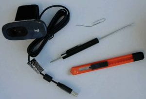
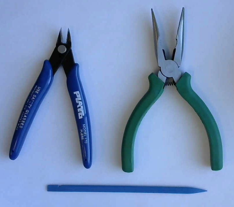
    Figure 1: tools necessary to perform the modifications.

    The main tools you need for this modification are a flat headed screwdriver to pry the front frame off, a phillips head screwdriver (No. 01) to remove some screws, and a knife to cut away the glob of glue. (It’s possible you might accomplish that with the flat head screwdriver.)

    Figure 2. Optional tools that might make the job easier.


    Some additional tools might make the job easier. A plastic spludger or something similar would be better for prying off the front frame without leaving marks. A pair of cutters could help with cutting away the slot (in Part B below) and pliers can help you remove the material from the slot.

  2. Remove the Frame:
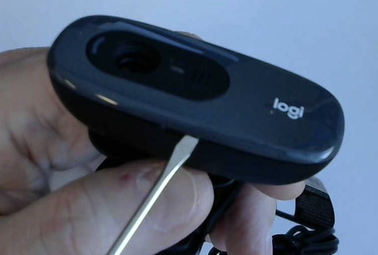
    Figure 3: Remove the “frame” on the front of the camera.

    Remove the frame on the front of the camera by prying, starting at the slot on the bottom for that purpose, using a flat head screwdriver or a spludger or similar tool.

  3. Remove face plate screws:
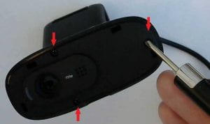
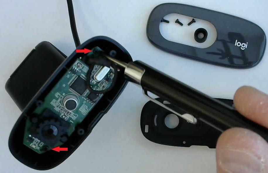
    Figure 4: Remove the face plate (front of camera housing) by unscrewing the three screws.

    Remove the three screws shown in Figure 4 and then remove the face plate.

  4. Microphone Sleeve:
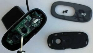
    Figure 5: Remove and save the rubber sleeve around the microphone.

    There is a round rubber sleeve around the microphone. Remove it and save it for reassembly. Don’t forget it – this is the easiest thing to overlook during reassembly.

  5. Circuit board:
    Figure 6: Remove the two screws (arrows) holding the circuit board to the case.

    Remove the two screws (shown in Figure 6) which attach the circuit board to the case. You need to do this to lift the circuit board out a bit to gain access to the side of the lens, under the gear wheel.

  6. Remove Glue Glob:
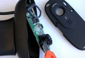
    Figure 7. Lift out the circuit board and find and remove the glob of glue.

    Locate the glob of glue that prevents the lens from turning to focus. It is likely on the side that is toward the top of the camera case. Using the knife or other tool, remove the glob of glue so that you can turn the lens with the gear wheel. Turning the lens lets you adjust the focus. You might find it helpful to turn the lens back and forth several times to make sure it is free to turn, and you might want to make sure that all the glue has been removed so that nothing catches or is impeded.

  7. Anchor Circuit Board: seat the circuit board back where it was and attach it to the case with the two screws shown in Figure 6. At this point re-assembly is the reverse of the steps above, but don’t forget the microphone sleeve.

After you have released the lens so that it can be turned to focus you have several choices: One is to adjust the focal distance to fit your needs and then reassemble the device, by going back through the steps above in reverse order. This is appropriate for an application where the camera will always be the same distance from the object, such as when used as a document camera.

Another option is to just leave the face plate off and expose the lens so that the focus can be adjusted anytime that is needed. This is the best choice if you will be using the camera for a variety of shots where the distance to the object can vary a lot. And besides, the bare circuit board looks cool and “technical”, and the activity LED may even give you some extra light for close-up shots.

In between these two, you can open a small slot in the face plate next to the lens, just big enough to let you adjust the focus using a paper clip. Then the camera looks almost like a stock C270, but the focus can be adjusted when needed.

B. Opening a Slot

Here is how to make a small slot so that you can adjust the focus with a paper clip even after the face plate and frame have been reinstalled. If you choose this route, it is a good idea to turn the lens back and forth multiple times to make sure that it is free to turn, because it is difficult to adjust the focus with a paper clip if the lens is binding as it is turned.
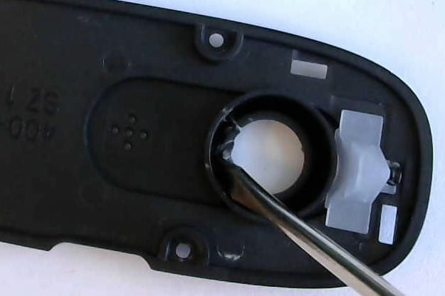
  1. Score Lens Opening:
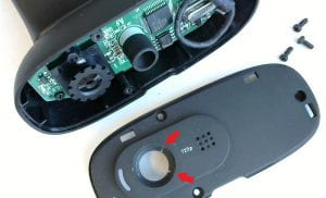
    Figure 8. Score the lens opening on one side to make the ends of the slot.

    Score or cut the lens opening on one side to make the ends of the slot.  I found the best positions were 45 degrees above and below horizontal, toward the microphone, as shown in Figure 8.  This leaves enough room to get the paper clip in and move the gear wheel by at least one tooth and slot.  Making several cuts in between +/- 45 degrees makes it very easy to remove the slot material.

  2. Remove Slot Material:
    Figure 9. View from the rear showing the tab between the cuts.  Pry out that tab.

    Pry out the material between the two cuts to make the slot.  You can push it with a screwdriver, or work it back and forth with pliers until it breaks off. If you’ve made several cuts the tabs should come off easily and relatively cleanly, because there is a natural thinning at the base of the tab you’ve created.  You may want to clean up the break a bit with the knife, but it’s not required (nobody but you will notice).
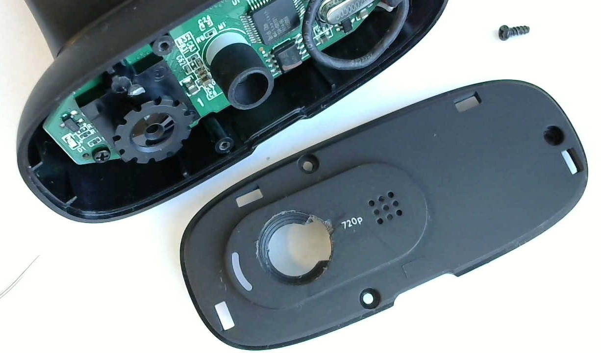
  3. Reassemble:
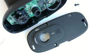
    Figure 10. Front view showing the tab removed to make the slot.

    Put the microphone sleeve back in place (remember that?) and then put the face plate back in place. Secure it with the three screws, and then put the frame back over the front.


References

I first found out about removing the glob of glue from the YouTube video Logitech c270 focus adjustment . I have not yet seen any other suggestions to make a slot for a paperclip, but I would not be surprised if someone else has had the same idea.

YSC-4 Electronic Clock

YSC-4 Electronic Clock

I’ve just completed building a small electronic clock from a kit, the YSC-4 kit from HiLetgo, which I was able to purchase from Amazon for under $9.1   My interest in this kit was to find something simple that is nevertheless good soldering practice for advanced beginners, and I was not disappointed.

Overview

The kit provides practice for a number of things that students should encounter:

  • an electrolytic capacitor  (requires specific polarity)
  • a buzzer (also has specific polarity)
  • a transistor  (three close leads, and requires proper orientation)
  • an IC socket, and the IC itself (oriented by a notch, and soldering close contacts)
  • segmented display digits (orientation and close contacts)
  • 2 momentary contact switches (orientation)
  • a network resistor pack (orientation and close contacts)

This version comes with a wall-wart with USB socket and a USB cord to the power socket.   I have since found a variation from another vendor (without the wall wart), which comes as a two-pack .  Yet another version, which costs slightly less, has just terminal posts for the power, though I think students are more likely to use their creation if it has the USB power cord.

It took me under an hour to assemble, even with a break for a snack. A beginner might take longer, but would have no difficulty. The kit included a piece of paper with a list of components and a circuit diagram, along with (somewhat confusing) instructions on how to set the time and alarms. The kit did not include step-by-step assembly instructions, but since the PCB is well marked it is clear what goes where, and so step-by-step instructions really are not necessary.  The one piece of advice to give to students is to start at the center of the board and work out, to make access to the leads easier when soldering.

Tips and Tricky Bits

Perhaps the trickiest thing in this kit was the  orientation of the network array; it has a dot on one end and markings on the PCB to show which end goes where.  We all missed that at first, so some boards had to have that component removed and resoldered.  Another tricky point was the switches, because it was not clear at first without testing with a meter which contacts are always joined and which are only joined when the button is pressed. Rotating the switches by 90 degrees will be the same as having the buttons always pressed down. As you might be able to see from the photo, the leads go on the sides, not the top and bottom.  It helps to think of the leads as two sets of flat straps that go across the switch from one side to the other.

Another thing that might trip up beginners is the orientation of the segmented display (the decimal points go at the bottom, as does the writing on the bottom side).  Unlike other PCB’s I have worked with, there are no components where you have to guess the orientation

Some other things to note:

  • This clock has a 24 hour display (no 12 hour display).
  • It will chime 3 times on the hour (unless you turn that off).
  • There are two alarms.   When initially turned on, the time  is 12:59 and the two alarms are enabled and set to 13:01 and 13:02.
  • There is no back-up battery, so you have to set the time (and alarms) again if you ever unplug it or it looses power somehow.

The display is very bright, but since the segments in the segmented display are white when not lit it can be hard to read the time from the bare clock face.  You can see this in the photo at the top of this post.  The solution to this is to cover the display with red or grey tinted plastic, so that only the lit red segments are visible.   I had a roll of red “tail light repair” tape which is 2″ wide and it fit perfectly, as shown here:

YSZ-4 clock with red tape over the display

However, we’ve learned not to put the tape on the display until the clock is working, as it obscures the decimal points at the bottom, leading to more problems with the display ending up upside-down.

We have had some success with replacing the buzzer with an LED, though it seems that the LED may eventually burn out, so it might be wise to add a resistor in series.  One student tried to put an LED in parallel with the buzzer, and that failed, but again maybe adding a resistor would make it work (that has not yet been tried).

Operating Instructions

The operating instructions that came with the kit are written in English, but appear to be a direct translation from Chinese and are somewhat confusing.   I found another set of instructions on the net that are also Chinese written in English, but differently.   From those and my own experience I was able to put together these operating instructions:

Switch S1 (on the left) is the Menu button.   An initial long press enters the first menu.  The menu pages are named A, B, C, D, E,  etc., and the menu letter is shown in the first digit of the display.   A short press on S1 takes you to the next menu.   You can only exit the menus by stepping through all of them; a long press will make them step through quickly  (but if you don’t remove pressure at the right time you’ll start the menu list over again).

In each menu, switch S2 (on the right) is the toggle/increment button.   On each menu page, us it to toggle a feature on or off, or to increment a numerical value.   For numerical values you can hold the button down and the count will go up automatically.

The menu pages are:

  • A – Hours, from 00 to 24  (there is no 12 hour option)
  • B – Minutes, from 00 to 59
  • C – Hourly chime.  If enabled the clock will beep 3 times on the hour, but only  between 08:00 and 20:00.
  • D – First Alarm on/off
  • E – First Alarm hour
  • F – First Alarm minutes
  • G – Second Alarm on/off
  • H – Second Alarm hour
  • I – Second Alarm minute

If an alarm is turned off then the menu will skip the hour and minutes items for that alarm. There is no way to exit the menu pages early; you must cycle through all of them to get back to normal operation.

Outside of the menus, a short press on switch S2 will change between displaying hours and minutes or displaying minutes and seconds. While the minutes and seconds are displayed, a long press on S2 will reset the seconds to zero, and then a short press on S2 will start the clock again from 00.

When an alarm is sounding there is no way to turn it off.  You just have to wait for it to finish.

Co-Curricular Transcript

Students at SUNY New Paltz can participate in a 4-Step training program in electronics soldering, where construction of this clock is the 4th step.  Once the clock is shown to work they can a certification added to their co-curricular transcript.  The student must request this certification; the instructor cannot give it without a request.

To request certification go to my.newpaltz.edu and click on “Student Engagement” in the main menu.  Then click on Co-Curricular Transcript in the Student Engagement menu.  In the search form enter “solder” in the Keyword field and press “Search.”   Click on the item and fill in the form.

3D Printed Case

Students can have a case for the clock 3D-Printed at our Hudson Valley Additive Manufacturing Center.  Payment must be made by credit or debit card after you submit the STL file.   The cost is around $1.30.  Under the “Resources” menu on the HVAMC page open the “Submit a Build” item and click on “Students”.    The STL file describing the case is YSZ-4_ClockCase.stl, but it will have to be renamed for submission (see the instructions on the submission form).  It was created with OpenSCAD.

More info…

The chip used in this kit is an Atmel AT89C2051 micro-controller, which is capable of much more than just being a clock. The vendor (or someone) must have flashed the IC with a simple clock program for this kit.  Maybe it would be possible to re-flash it to allow for 12 hour mode. Anybody up for this challenge?

Also, I tried powering it with a single 3.2 Volt coin battery, and that worked initially, but drained the battery very quickly, so it’s not really a viable option.

These instructions by clobber24 on Instructables for a C51 4-Bit Clock  apply, except for the power jack.  That page also links to 3D printed cases.  He printed a battery case for three AAA batteries, which he says worked, but he does not report on battery life.

Notes

  1. in 2019.  The cost is slightly higher now.

The Compartment Box Trick

Figure 1: Plastic compartment box.
Figure 1: Compartment Box

Have you ever taken something apart and then put it back together and had parts left over? Me too. Sometimes it’s something I know isn’t needed, but it’s still better to get everything back in the right place.  A few years ago I discovered a little trick that helps me do that.

What I do is I start with an empty plastic compartment box (see Figure 1),  and as I take the thing apart I put the various screws and small parts into successive compartments.  When I’m done with disassembly I have a complete set of parts, organized in the order they came out of the thing (see Figure 2).   And then when it’s time to re-assemble the thing, I can just go backwards through the compartments and I have everything that I need in the order that I need it, and I don’t forget anything.

Figure 2: Compartment box in use


You don’t have to have a special plastic box for this, because an egg carton works just as well.   (That’s what I started with, but I got the plastic compartment boxes when they were on sale at the store.)   However, one great advantage of the compartment box is that you can close it when you are done, or when you have to take a break from the work, and you are in less danger of losing everything all over the place if someone bumps into it or bumps into the bench.


Just don’t let anybody fill up the box with parts. You need to have an EMPTY plastic compartment box available when you start taking the thing apart.   Think of it as another one of the tools you’ll use to fix whatever it is you are fixing, rather than as storage.

Repairing a Cenco 33031 Power Supply

Figure 1: Cenco 33031 Low Voltage Power Supply

by Laurence Rowe and Eric Myers

We use the Cenco 33031 Low Voltage Power Supply (Figure 1) for several of our electricity and magnetism labs.   It can provide variable DC up to 6 Volts at up to  5 Amps, and it can provide a steady AC voltage at around 22 VAC.

Unfortunately, our students sometimes exceed the 5 Amp DC limit and damage the supply, rendering it useless.   The problem is almost always the main power transistor.   We have even tried adding a 5A fuse in the DC output circuit, but the power transistor blows out much more quickly than a fuse.  We recently switched some devices to use 4A fuses, with some success, but in the case of a short circuit this small difference will probably not matter; the power transistor will blow first.

Presented below are step-by-step instructions for replacing the power transistor.  Another component that might need to be replaced is an LM317 voltage regulator.   We will add instructions for replacing that sometime in the future.   Meanwhile, when the DC fails, the first thing to try is replacing the power transistor.

Preparations

Figure 2: 2N3055 Power Transitor
Figure 2: 2N3055 

Before you get started, you will need the replacement part(s) and some tools:

  • Phillips screw driver
  • Soldering iron
  • 2N3055 power transistor (Figure 2)
  • Thermal paste
  • Replacement mica heat shield for the 2N3055
  • LM317T voltage regulator (optional)

You may be able to re-use the mica heat shield, but you won’t know that for sure until you remove the power transistor, so you’ll want to have one on-hand just in case.

While it is also optional, it can be helpful to use a plastic compartment box  to hold the screws and other parts during disassembly.    If you don’t have a plastic box, an egg carton works just as well.

See the addendum below for an estimate of the time required for the repair.

 Replacing the Power Transistor

  1. Remove the 8 small case screws (see Figure3), gently lift the cover, and slide it to the right.

    Figure 3: Case screws.
    Figure 3: Case screws.
  2. Remove the 2 screws holding the heat sink to the bottom of the case (shown in Figure 4).  Be careful not to bend or break the leads on the voltage regulator, which is the black chip with 3 leads which is attached to the heat sink.   Those leads can break off easily.

    Figure 4: Heat sink screws.
    Figure 4: Heat sink screws.
  3. You will find two components connected to the heat sink.   The power transistor sits on one side of the heat sink and is connected to it by screws at both ends.    On the other side of the heat sink is an LM317T voltage regulator, a smaller black chip with 3 leads. There are tie wraps around bundles of wires for neatness. Remove these as needed (and replace on reassembly if you can).Start with the screw at the far “plain” end of the transistor – the one without a wire attached (see Figure 5).  Remove and save the nut, washer, lock washer, and the screw.

    Figure 5: "Plain" transistor screw - no wire.
    Figure 5: First transistor screw.
  4. Then go to the other end of the transistor, and remove the top nut, washer, lock washer, and the wire lug.  You can’t see the color of the wire in the picture because of the yellow insulating sleeve, but you’ll easily see that this is the white wire.  There is another nut and washer underneath the first.
  5. Heat the solder and remove the red and orange wires from the power transistor, shown in Figure 6.  Take care to avoid excess heat or you will damage the plastic insulator between the two wires.
    Figure 6. Red and Orange wires connecting to Power Transistor.

    Note the placement of the wires.   The thicker red wire is farthest from the voltage regulator (black chip) and the slightly thinner orange wire is closer to the voltage regulator.

  6. Now remove the remaining nut, washer and screw from the power transistor and save these.
  7. Once the wires have been removed, you can clip the leads on the power transistor as close to the heat sink as possible to facilitate removal.
  8. Pull up on the plastic insulator by the center tab (the part which was between the red and orange wires).  Push the cut leads from the back to release the transistor.
  9. You can leave the mica insulator in place if it is still contacting the heats sink.  If it comes off the heat sink then you’ll need to gently clean the surface and either reuse it (if intact) or replace it.   Be careful, the mica breaks easily.
  10. In any case, spread a fresh layer of heat compound over the mica insulator to make a good thermal connection to the new power transistor.
  11. Place the new power transistor where the old one was, with the leads through the holes in the heat sink and through the holes in the plastic insulator.   It may not be obvious at first, but there is a slight asymmetry — the leads are offset from the centerline — so that you can only put the transistor in one way, and only orient the plastic insulator one way.
  12. Reinstall the screws at both ends of the power transistors.   Keep in mind that the longer screw goes on the end that will connect to the wire lug on the white wire.   It’s easiest to connect the wire lug last, when the other screws are holding the power transistor in place.
  13. Re-solder the orange and red wires to the power transistor.   As shown in Figure 6, the orange wire is closest to the voltage regulator (black chip) and the red wire is farthest from it.
  14. Test the repair before you screw the heat sink back in place or the cover.  The power supply should now go up to at least 6VDC when turned all the way up.   If not, you’ll have to check your work more carefully.   You may have to replace the voltage regulator too.
  15. Reattach the heat sink to the case.
  16. Close the case with the 8 case screws.

The last thing we will mention is that some students have taken to turning the power supply on it’s side, so that the “top” faces forward instead of upward.   The case screws can then scratch the table, so I’ve been adding rubber feet next to the case screws to prevent such scratches.

Addendum

12 March 2019:   The last time I made this repair it took me 35 minutes from cracking the case open to closing it up (all 8 screws), and I had done it before, but not recently.   If I was to do another immediately I could probably get the time under half an hour, but if you’ve never done this before then plan to spend at least twice as long.


Skip to toolbar