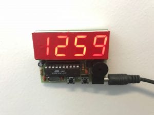
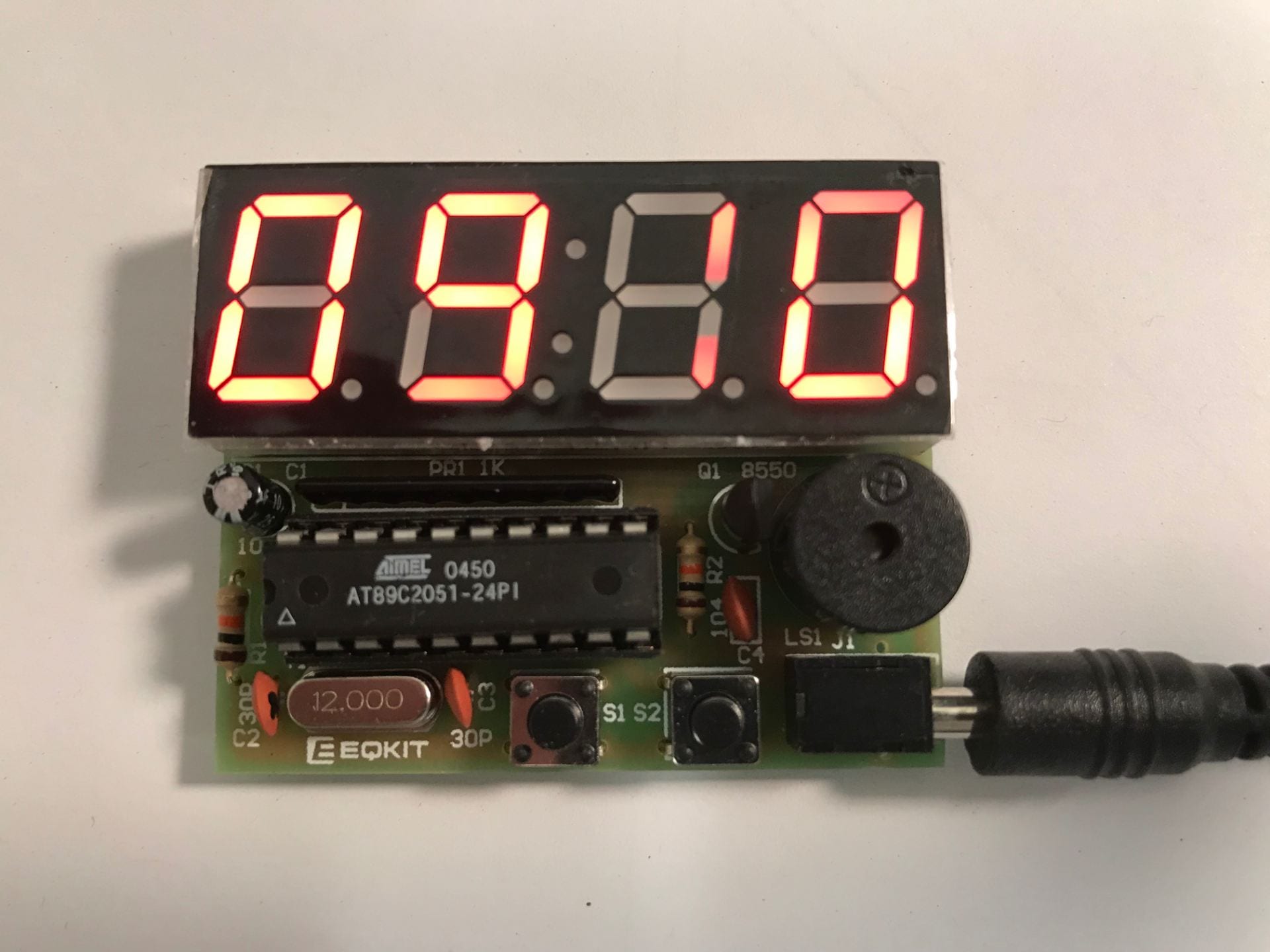
I’ve just completed building a small electronic clock from a kit, the YSC-4 kit from HiLetgo, which I was able to purchase from Amazon for under $9.1 My interest in this kit was to find something simple that is nevertheless good soldering practice for advanced beginners, and I was not disappointed.
Overview
The kit provides practice for a number of things that students should encounter:
- an electrolytic capacitor (requires specific polarity)
- a buzzer (also has specific polarity)
- a transistor (three close leads, and requires proper orientation)
- an IC socket, and the IC itself (oriented by a notch, and soldering close contacts)
- segmented display digits (orientation and close contacts)
- 2 momentary contact switches (orientation)
- a network resistor pack (orientation and close contacts)
This version comes with a wall-wart with USB socket and a USB cord to the power socket. I have since found a variation from another vendor (without the wall wart), which comes as a two-pack . Yet another version, which costs slightly less, has just terminal posts for the power, though I think students are more likely to use their creation if it has the USB power cord.
It took me under an hour to assemble, even with a break for a snack. A beginner might take longer, but would have no difficulty. The kit included a piece of paper with a list of components and a circuit diagram, along with (somewhat confusing) instructions on how to set the time and alarms. The kit did not include step-by-step assembly instructions, but since the PCB is well marked it is clear what goes where, and so step-by-step instructions really are not necessary. The one piece of advice to give to students is to start at the center of the board and work out, to make access to the leads easier when soldering.
Tips and Tricky Bits
Perhaps the trickiest thing in this kit was the orientation of the network array; it has a dot on one end and markings on the PCB to show which end goes where. We all missed that at first, so some boards had to have that component removed and resoldered. Another tricky point was the switches, because it was not clear at first without testing with a meter which contacts are always joined and which are only joined when the button is pressed. Rotating the switches by 90 degrees will be the same as having the buttons always pressed down. As you might be able to see from the photo, the leads go on the sides, not the top and bottom. It helps to think of the leads as two sets of flat straps that go across the switch from one side to the other.
Another thing that might trip up beginners is the orientation of the segmented display (the decimal points go at the bottom, as does the writing on the bottom side). Unlike other PCB’s I have worked with, there are no components where you have to guess the orientation
Some other things to note:
- This clock has a 24 hour display (no 12 hour display).
- It will chime 3 times on the hour (unless you turn that off).
- There are two alarms. When initially turned on, the time is 12:59 and the two alarms are enabled and set to 13:01 and 13:02.
- There is no back-up battery, so you have to set the time (and alarms) again if you ever unplug it or it looses power somehow.
The display is very bright, but since the segments in the segmented display are white when not lit it can be hard to read the time from the bare clock face. You can see this in the photo at the top of this post. The solution to this is to cover the display with red or grey tinted plastic, so that only the lit red segments are visible. I had a roll of red “tail light repair” tape which is 2″ wide and it fit perfectly, as shown here:

However, we’ve learned not to put the tape on the display until the clock is working, as it obscures the decimal points at the bottom, leading to more problems with the display ending up upside-down.
We have had some success with replacing the buzzer with an LED, though it seems that the LED may eventually burn out, so it might be wise to add a resistor in series. One student tried to put an LED in parallel with the buzzer, and that failed, but again maybe adding a resistor would make it work (that has not yet been tried).
Operating Instructions
The operating instructions that came with the kit are written in English, but appear to be a direct translation from Chinese and are somewhat confusing. I found another set of instructions on the net that are also Chinese written in English, but differently. From those and my own experience I was able to put together these operating instructions:
Switch S1 (on the left) is the Menu button. An initial long press enters the first menu. The menu pages are named A, B, C, D, E, etc., and the menu letter is shown in the first digit of the display. A short press on S1 takes you to the next menu. You can only exit the menus by stepping through all of them; a long press will make them step through quickly (but if you don’t remove pressure at the right time you’ll start the menu list over again).
In each menu, switch S2 (on the right) is the toggle/increment button. On each menu page, us it to toggle a feature on or off, or to increment a numerical value. For numerical values you can hold the button down and the count will go up automatically.
The menu pages are:
- A – Hours, from 00 to 24 (there is no 12 hour option)
- B – Minutes, from 00 to 59
- C – Hourly chime. If enabled the clock will beep 3 times on the hour, but only between 08:00 and 20:00.
- D – First Alarm on/off
- E – First Alarm hour
- F – First Alarm minutes
- G – Second Alarm on/off
- H – Second Alarm hour
- I – Second Alarm minute
If an alarm is turned off then the menu will skip the hour and minutes items for that alarm. There is no way to exit the menu pages early; you must cycle through all of them to get back to normal operation.
Outside of the menus, a short press on switch S2 will change between displaying hours and minutes or displaying minutes and seconds. While the minutes and seconds are displayed, a long press on S2 will reset the seconds to zero, and then a short press on S2 will start the clock again from 00.
When an alarm is sounding there is no way to turn it off. You just have to wait for it to finish.
Co-Curricular Transcript
Students at SUNY New Paltz can participate in a 4-Step training program in electronics soldering, where construction of this clock is the 4th step. Once the clock is shown to work they can a certification added to their co-curricular transcript. The student must request this certification; the instructor cannot give it without a request.
To request certification go to my.newpaltz.edu and click on “Student Engagement” in the main menu. Then click on Co-Curricular Transcript in the Student Engagement menu. In the search form enter “solder” in the Keyword field and press “Search.” Click on the item and fill in the form.
3D Printed Case
Students can have a case for the clock 3D-Printed at our Hudson Valley Additive Manufacturing Center. Payment must be made by credit or debit card after you submit the STL file. The cost is around $1.30. Under the “Resources” menu on the HVAMC page open the “Submit a Build” item and click on “Students”. The STL file describing the case is YSZ-4_ClockCase.stl, but it will have to be renamed for submission (see the instructions on the submission form). It was created with OpenSCAD.
More info…
The chip used in this kit is an Atmel AT89C2051 micro-controller, which is capable of much more than just being a clock. The vendor (or someone) must have flashed the IC with a simple clock program for this kit. Maybe it would be possible to re-flash it to allow for 12 hour mode. Anybody up for this challenge?
Also, I tried powering it with a single 3.2 Volt coin battery, and that worked initially, but drained the battery very quickly, so it’s not really a viable option.
These instructions by clobber24 on Instructables for a C51 4-Bit Clock apply, except for the power jack. That page also links to 3D printed cases. He printed a battery case for three AAA batteries, which he says worked, but he does not report on battery life.
Notes
- in 2019. The cost is slightly higher now. ↩
